


Chapter 4 Menu Operations
4-14 Chapter 4 Menu Operations
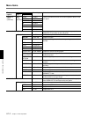
Menu Items
Display Char. display Contents
Layer 2 Layer 3 Layer 4
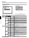
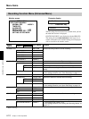
PARALLEL INm MENU >>>Menu
Function the same as those on the menu operation block on the
SET/YES >>>Set/Yes
front panel.
RESET/NO >>>Reset/No
B >>>Left
b >>>Right
v >>>Down
V >>>Up
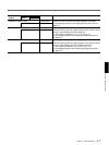
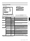
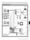
PARALLEL OUTPUT >ParaOutput For assigning a function to each output pin (8 outputs) of the
PARALLEL I/O connector on the rear panel.
OUTm (n PIN) >>n PIN m = 1 to 8, n = pin number 15 to 18, 33 to 36
NO USE >>>No use Outputs no signal.
STOP >>>Stop St Outputs status signals to indicate the operating statuses of the
recorder.
REC >>>Rec St
PLAY >>>Play St
F.FWD >>>FFWD St
REW >>>REW St
SERIES REC >>>SeriesRec Outputs the Series-recording signal.
TIME >>>Time Set Outputs the clock set signal when the internal clock counts 00
ADJUSTMENT minute 00 second.
ALARM >>>AlmRetrn Outputs a signal upon return from alarm recording
RETURN
ALARM >>>Alarm Outputs a status signal to indicate that alarm recording is in
progress.
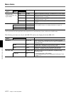
TAPE END >>>Tape End Outputs a signal when tape end is reached during
recording.
TAPE EXIST >>>TapeExst Outputs a signal when a cassette is in the recorder.
ERROR >>>Error Outputs a signal when an error occurs in the recorder.
VIDEO LOSS >>>Videolos Outputs a signal when the video input from a camera set to
“CONNECT” is lost.
PRE END >>>Pre-end Outputs a signal when the tape remaining becomes less than 3
minutes based on the tape length.
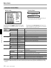
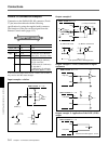
PARALLEL OUT VOLTAGE >POutVolt For setting the output voltage from each output pin (8 outputs)
of the PARALLEL I/O connector on the rear panel.
OUTm (n PIN) >>n PIN m = 1 to 8, n = pin number 15 to 18, 33 to 36
OPEN >>>Open Outputs with OPEN/0 V.
5V >>>5V Outputs with 5 V.
12V >>>12V Outputs with 12 V.
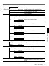
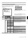
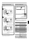
INPUT
(continued)
(n PIN)
(continued)