


– 13 –
ICX274AQ
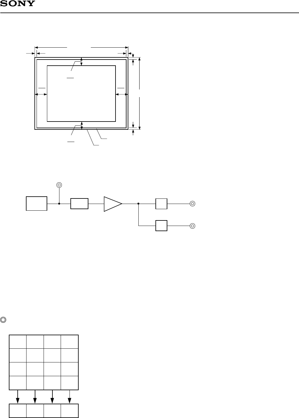
Image Sensor Characteristics Measurement Method
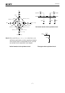
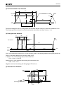
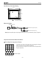
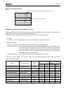
Color coding of this image sensor & Readout
The primary color filters of this image sensor are arranged in the layout
shown in the figure on the left (Bayer arrangement).
Gr and Gb denote the G signals on the same line as the R signal and the
B signal, respectively.
Gb B Gb B
RGrRGr
Gb B Gb B
RGrRGr
Horizontal register
Color Coding Diagram
4
V
10
4
8
8
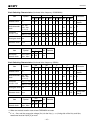
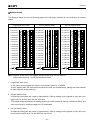
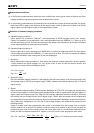
Ignored region
Effective pixel region
Zone 0, I
Zone II, II’
V
10
H
8
H
8
1628 (H)
1236 (V)
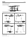
Zone Definition of Video Signal Shading
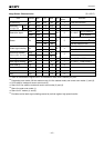
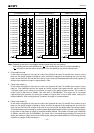
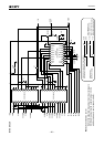
Measurement System
CCD C.D.S
S/H
S/H
AMP
CCD signal output [
∗
A]
Gr/Gb channel signal output [
∗
B]
R/B channel signal output [
∗
C]
Note) Adjust the amplifier gain so that the gain between [
∗
A] and [
∗
B], and between [
∗
A] and [
∗
C] equals 1.