


– 18 –
ICX274AQ
Measurement conditions
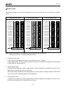
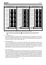
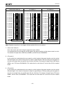
(1) In the following measurements, the device drive conditions are at the typical values of the bias and clock
voltage conditions, and the progressive scan readout mode is used.
(2) In the following measurements, spot blemishes are excluded and, unless otherwise specified, the optical
black level (OB) is used as the reference for the signal output, which is taken as the value of the Gr/Gb
signal output or the R/B signal output of the measurement system.
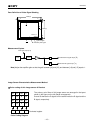
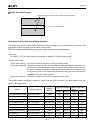
Definition of standard imaging conditions
(1) Standard imaging condition I:
Use a pattern box (luminance: 706cd/m
2
, color temperature of 3200K halogen source) as a subject.
(Pattern for evaluation is not applicable.) Use a testing standard lens with CM500S (t = 1.0mm) as an IR
cut filter and image at F5.6. The luminous intensity to the sensor receiving surface at this point is defined
as the standard sensitivity testing luminous intensity.
(2) Standard imaging condition II:
Image a light source (color temperature of 3200K) with a uniformity of brightness within 2% at all angles.
Use a testing standard lens with CM500S (t = 1.0mm) as an IR cut filter. The luminous intensity is adjusted
to the value indicated in each testing item by the lens diaphragm.
1. Sensitivity
Set to the standard imaging condition I. After setting the electronic shutter mode with a shutter speed of
1/100s, measure the signal voltages (VGr, VGb) at the center of each Gr and Gb channel screen, and
substitute the values into the following formulas.
VG = (VGr + VGb)/2
Sg = VG × [mV]
2. Saturation signal
Set to the standard imaging condition II. After adjusting the luminous intensity to 20 times the intensity with
the average value of the G channel signal output, 150mV, measure the minimum values of the G, R and B
signal outputs.
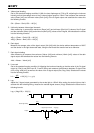
3. Smear
Set to standard imaging condition II. With the lens diaphragm at F5.6 to F8, first adjust the average value
of the Gr signal output to 150mV. Measure the average values of the Gr signal output, Gb signal output, R
signal output and B signal output (Gra, Gba, Ra, Ba), and then adjust the luminous intensity to 500 times
the intensity with the average value of the Gr signal output, 150mV. After the readout clock is stopped and
the charge drain is executed by the electronic shutter at the respective H blankings, measure the maximum
value (Vsm [mV]) independent of the Gr, Gb, R and B signal outputs, and substitute the values into the
following formula.
Smear in modes other than progressive scan mode is calculated from the storage time and signal
addition method. As a result, 2-line addition mode and center scan modes (2) and (3) are the same as
progressive scan mode, 2/4-line readout mode and center scan mode (1) are two times progressive scan
mode, and 2/8-line readout mode and AF modes (1) and (2) are four times progressive scan mode.
Sm = 20 × log
(
Vsm ÷ × ×
)
[dB] (1/10V method conversion value)
100
30
1
10
1
500
Gra + Gba + Ra + Ba
4