


– 19 –
ICX274AQ
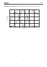
4. Video signal shading
Set to the standard imaging condition II. With the lens diaphragm at F5.6 to F8, adjusting the luminous
intensity so that the average value of the G channel signal output is 150mV. Then measure the maximum
value (Gmax [mV]) and minimum value (Gmin [mV]) of the G signal output and substitute the values into
the following formula.
SH = (Gmax – Gmin)/150 × 100 [%]
5. Uniformity between video signal channels
After measuring 4, measure the maximum (Rmax [mV]) and minimum (Rmin [mV]) values of the R signal
and the maximum (Bmax [mV]) and minimum (Bmin [mV]) values of the B signal, and substitute the values
into the following formulas.
∆Srg = (Rmax – Rmin)/150 × 100 [%]
∆Sbg = (Bmax – Bmin)/150 × 100 [%]
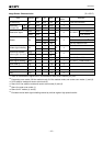
6. Dark signal
Measure the average value of the signal output (Vdt [mV]) with the device ambient temperature of 60°C
and the device in the light-obstructed state, using the horizontal idle transfer level as a reference.
7. Dark signal shading
After measuring 6, measure the maximum (Vdmax [mV]) and minimum (Vdmin [mV]) values of the dark
signal output and substitute the values into the following formula.
∆Vdt = Vdmax – Vdmin [mV]
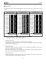
8. Line crawl
Set to the standard imaging condition II. Adjusting the luminous intensity so that the value of the Gr signal
output is 150mV, and then insert R, G and B filters and measure the difference between G signal lines
(∆Glr, ∆Glg, ∆Glb [mV]) as well as the value of the G signal output (Gar, Gag, Gab). Substitute the values
into the following formula.
Lci = × 100 [%] (i = r, g, b)
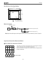
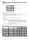
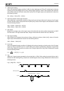
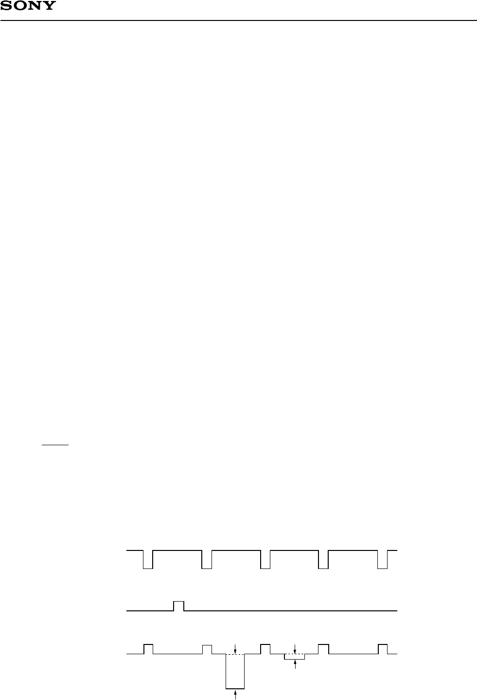
9. Lag
Adjust the Y signal output generated by the strobe light to 150mV. After setting the strobe light so that it
strobes with the following timing, measure the residual signal amount (Vlag). Substitute the value into the
following formula.
Lag = (Vlag/150) × 100 [%]
∆Gli
Gai
VD
Light
Output
Strobe light timing
Vlag (lag)
Y signal output 150mV