


– 4 –
ICX274AQ
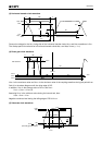
Bias Conditions
∗
1
Progressive scan mode, 2/8-line readout mode, 2/4-line readout mode, center scan modes (1) and (3),
and AF modes (1) and (2)
∗
2
2-line addition mode and center scan mode (2)
∗
3
VL setting is the VVL voltage of the vertical clock waveform, or the same voltage as the VL power supply
for the V driver should be used.
∗
4
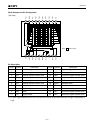
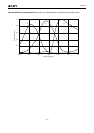
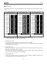
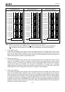
Substrate voltage (VSUB2) setting value indication
The substrate voltage (VSUB) for modes without line addition is generated internally.
The substrate voltage setting value for use with vertical 2-line addition is indicated by a code on the
bottom surface of the image sensor. Adjust the substrate voltage to the indicated voltage.
VSUB2 code – 1-digit indication
↑
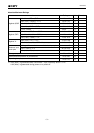
VSUB2 code
The code and the actual value correspond as follows.
[Example] "h" indicates a VSUB2 setting of 11.6V.
∗
5
Do not apply a DC bias to the reset gate clock pin, because a DC bias is generated within the CCD.
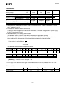
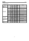
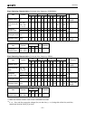
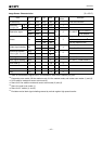
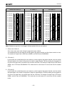
DC characteristics
Supply current
Item
IDD
Symbol
10.0
Min. Unit RemarksTyp. Max.
mA13.07.0
J
11.8
K
12.0
L
12.2
m
12.4
N
12.6
P
12.8
R
13.0
S
13.2
U
13.4
V
13.6
W
13.8
X
14.0
Y
14.2
Z
14.4
VSUB2 code
Actual value
1
8.8
2
9.0
3
9.2
4
9.4
6
9.6
7
9.8
8
10.0
9
10.2
A
10.4
C
10.6
d
10.8
E
11.0
f
11.2
G
11.4
h
11.6
VSUB2 code
Actual value
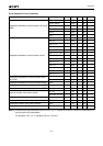
Supply voltage
Protective transistor bias
Substrate voltage
adjustment range
Substrate voltage adjustment accuracy
Reset gate clock
Item
VDD
VL
VSUB
VSUB2
∆VSUB
φRG
Symbol
15.0
∗
3
Internally generated value
Indicated
voltage
∗
5
Min.
V
V
V
V
Unit
∗
4
RemarksTyp. Max.
No line addition
∗
1
2-line addition
∗
2
14.55
8.8
Indicated
voltage – 0.2
15.45
14.4
Indicated
voltage + 0.2