


– 12 –
ICX418AKL
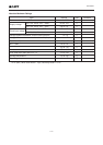
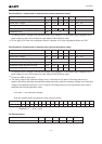
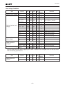
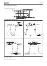
Image Sensor Characteristics Measurement Method
Measurement conditions
1) In the following measurements, the device drive conditions are at the typical values of the bias and clock
voltage conditions. (when used with substrate bias external adjustment, set the substrate voltage to the
value indicated on the device.)
2) In the following measurements, spot blemishes are excluded and, unless otherwise specified, the optical
black level (OB) is used as the reference for the signal output, which is taken as the value of Y signal output
or chroma signal output of the measurement system.
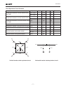
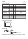
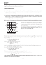
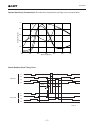
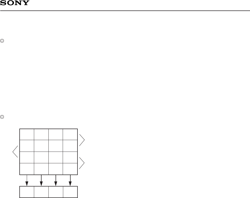
Color coding of this image sensor & Composition of luminance (Y) and chroma (color difference) signals
As shown in the left figure, fields are read out. The charge is
mixed by pairs such as A1 and A2 in the A field. (pairs such
as B in the B field)
As a result, the sequence of charges output as signals from
the horizontal shift register (Hreg) is, for line A1, (G + Cy),
(Mg + Ye), (G + Cy), and (Mg + Ye).
These signals are processed to form the Y signal and chroma (color difference) signal. The Y signal is formed
by adding adjacent signals, and the chroma signal is formed by subtracting adjacent signals. In other words,
the approximation:
Y = {(G + Cy) + (Mg + Ye)} × 1/2
= 1/2 {2B + 3G + 2R}
is used for the Y signal, and the approximation:
R – Y = {(Mg + Ye) – (G + Cy)}
= {2R – G}
is used for the chroma (color difference) signal. For line A2, the signals output from Hreg in sequence are
(Mg + Cy), (G + Ye), (Mg + Cy), (G + Ye).
The Y signal is formed from these signals as follows:
Y = {(G + Ye) + (Mg + Cy)} × 1/2
= 1/2 {2B + 3G + 2R}
This is balanced since it is formed in the same way as for line A1.
In a like manner, the chroma (color difference) signal is approximated as follows:
– (B – Y) = {(G + Ye) – (Mg + Cy)}
= – {2B – G}
In other words, the chroma signal can be retrieved according to the sequence of lines from R – Y and – (B – Y)
in alternation. This is also true for the B field.
Cy Ye Cy Ye
GMgGMg
Cy Ye Cy Ye
Mg G Mg G
B
A1
A2
Hreg
Color Coding Diagram