


– 14 –
ICX418AKL
7. Dark signal shading
After measuring 6, measure the maximum (Ydmax [mV]) and minimum (Ydmin [mV]) values of the dark
signal output and substitute the values into the following formula.
∆Ydt = Ydmax – Ydmin [mV]
8. Flicker
1) Fy
Set to standard imaging condition II. Adjust the luminous intensity so that the average value of the Y signal
output is 200mV, and then measure the difference in the signal level between fields (∆Yf [mV]). Then
substitute the value into the following formula.
Fy = (∆Yf/200) × 100 [%]
2) Fcr, Fcb
Set to standard imaging condition II. Adjust the luminous intensity so that the average value of the Y signal
output is 200mV, insert an R or B filter, and then measure both the difference in the signal level between
fields of the chroma signal (∆Cr, ∆Cb) as well as the average value of the chroma signal output (CAr, CAb).
Substitute the values into the following formula.
Fci = (∆Ci/CAi) × 100 [%] (i = r, b)
9. Line crawls
Set to standard imaging condition II. Adjust the luminous intensity so that the average value of the Y signal
output is 200mV, and then insert a white subject and R, G, and B filters and measure the difference
between Y signal lines for the same field (∆Ylw, ∆Ylr, ∆Ylg, ∆Ylb [mV]). Substitute the values into the
following formula.
Lci = (∆Yli/200) × 100 [%] (i = w, r, g, b)
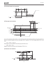
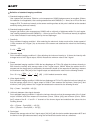
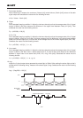
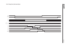
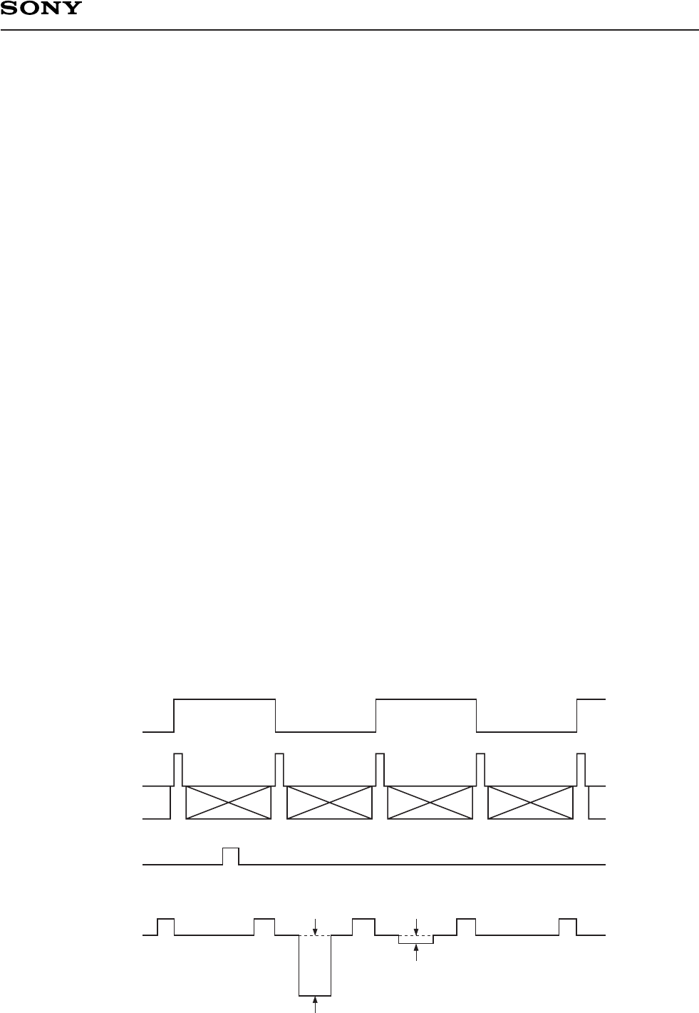
10. Lag
Adjust the Y signal output value generated by strobe light to 200mV. After setting the strobe light so that it
strobes with the following timing, measure the residual signal (Ylag). Substitute the value into the following
formula.
Lag = (Ylag/200) × 100 [%]
Light
Y signal output 200mV Ylag (lag)
FLD
V1
Strobe light
timing
Output