


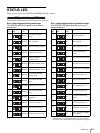
I/O Port
27
I/O Port
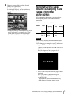
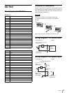
Pin Assignment of I/O Port
Sensor In
Alarm Out
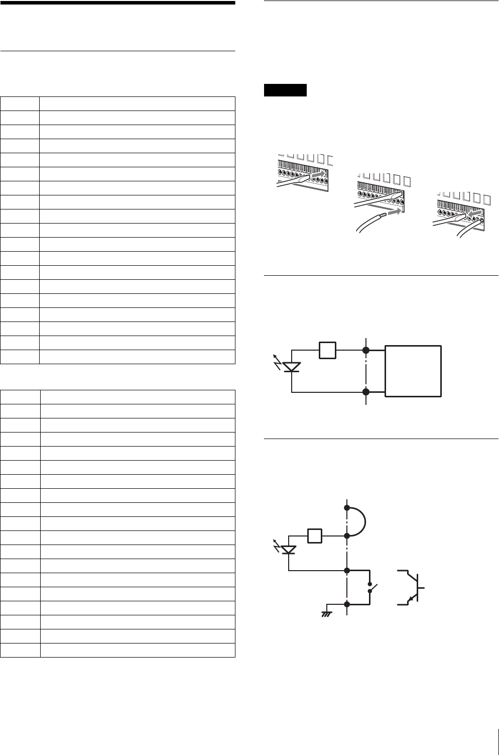
Using the I/O Receptacle
Insert a small slotted screwdriver into the upper or lower
slot of the hole you want to connect a wire to (AWG No.
28 to 18). Hold down the screwdriver and insert the wire,
then release the screwdriver.
Caution
Do not use excessive force when inserting the
screwdriver into the slot. Doing so may result in
damage.
Repeat this procedure to connect all required wires.
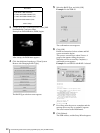
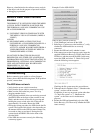
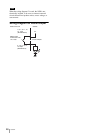
Wiring Diagram 1 for Sensor Input
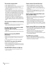
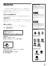
Wiring Diagram 2 for Sensor Input
Pin NO. SENSOR IN
13.3 v
2IN_8 –
3IN_8 +
4IN_7 –
5IN_7 +
6IN_6 –
7IN_6 +
8IN_5 –
9IN_5 +
10 IN_4 –
11 IN_4 +
12 IN_3 –
13 IN_3 +
14 IN_2 –
15 IN_2 +
16 IN_1 –
17 IN_1 +
18 GND
Pin NO. ALARM OUT
1 GND
2 OUT_8 –
3 OUT_8 +
4 OUT_7 –
5 OUT_7 +
6 OUT_6 –
7 OUT_6 +
8 OUT_5 –
9 OUT_5 +
10 OUT_4 –
11 OUT_4 +
12 OUT_3 –
13 OUT_3 +
14 OUT_2 –
15 OUT_2 +
16 OUT_1 –
17 OUT_1 +
18 3.3 v
1
2
3
3, 5, 7, 9, 11, 13, 15, 17pin
(SENSOR IN+)
2, 4, 6, 8, 10, 12, 14, 16pin
(SENSOR IN-)
2.35 kΩ
Sensor
device
Output:
3.3 to 24 V
DC
Inside of this unit Outside
3, 5, 7, 9, 11, 13, 15,
17pin
(SENSOR IN+)
2, 4, 6, 8, 10, 12, 14,
16pin
(SENSOR IN-)
2.35 kΩ
Wire
Inside of this unit Outside
1 pin (VDD) (200 mA max)
Mechanical
switch
18pin (GND)
GND
or
Open collector
output device