


Ver.1.02
Practical operation example
9. Specification
[
[[
[Electronic Specification]
]]
]
(1) Image sensor CMOS image sensor
• Total pixel 1280(H) x 1024(V)
• Active pixel 1240(H) x 1024(V)
• Pixel size 6.7(H) x 6.7(V) micro m
• Image area 8.308mm(H) x 6.854mm(V)
• Driving frequency 39.3216 MHz
(2) Scanning line 1024 lines
(3) Scanning system Progressive
(4) Frame rate 16 fps(Exposure time: 62.5 micro sec)
(5) Sync system Internal
(6) Aspect ratio 5 : 4
(7) Subject illumination 2600lx,F5.6(3100K)(Exposure time: Approx 16 msec)
(8) Video output time Approx. 62.2 msec
(9) Interface Conforms to IEEE Std. 1394a-2000
Transfer speed 400Mbps
(10) Video mode Format7/Special format (in WOI) Mono 8bit
(11) Protocol Conforms to 1394-based Digital Camera Specification ver.1.3
(12) Input signal TRIG (Shutter Trigger) 3.3V CMOS level
Grabbing timing Falling edge detection
Pulse width Minimum : 5 micro sec
Max : no limit
(13) Electronic shutter Shutter speed (preset inside the camera) selection via communication
command 1 through 4000 (approx. 62.5 micro sec through 1 sec)
(14) Shutter mode Global shutter
(15) Random Trigger RTS operation is available by external trigger input. Shutter speed
Shutter preset or shutter speed control by pulse width is available.
Mode 0 Shutter speed preset mode (preset inside camera)
Mode 1 Shutter speed can be controlled via shutter trigger pulse width.
The camera starts light-exposure at the falling edge timing and ends it at
the rising edge timing.
(16) Power supply DC+8V through DC+30V (IEEE1394 cable power supply)
(17) Power condition Approx. 1.5W (at +30V)
Approx. 1.4W (at +12V)
Approx. 1.4W (at +8V)
[
[[
[Mechanical Specification]
]]
]
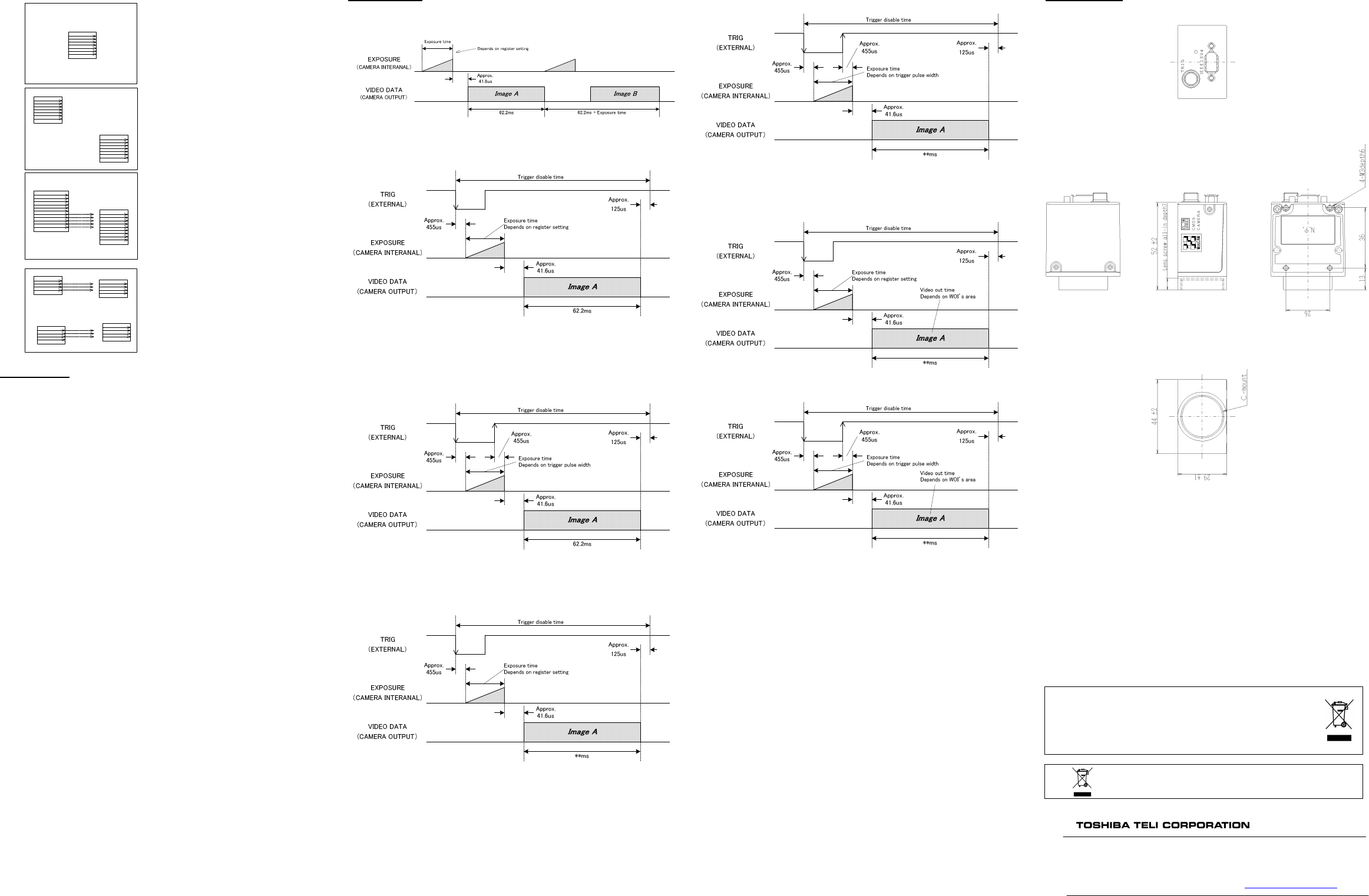
(1) External dimension 44(W)×29(H)×52(D) mm(Without projection)
(2) Weight Approx. 120 g
(3) Lens mount C-mount
(4) Flange back 17.526 mm
(5) Chassis grounding Between Connector shell and FG Continuity provided
/insulation Between FG and SG Continuity not provided
[
[[
[Use environmental conditions]
]]
]
(1) Ambient condition
Temperature:
Performance guaranteed From 0 through 40 degrees Celsius
Operation guaranteed From –5 through 45 degrees Celsius
Preservation From –20 through 60 degrees Celsius
Humidity:
Performance guaranteed From 20 through 80 % (No condensing)
Operation guaranteed From 20 through 80 % (No condensing)
Preservation From 20 through 95 % (No condensing)
[
[[
[Interface specification]
]]
]
Please contact our sales person about interface specification.
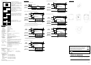
10. Timing Chart
(1) Normal shutter mode (Format 7 mode 0)
(2) Random Trigger Shutter mode (Fix mode, Format 7 mode 0)
Shutter speed depends on the internal resister setting value.
After trigger IN, next trigger signal is not acceptable until the readout is completed.
(3) Random Trigger Shutter (Pulse width control, Format 7 mode 0)
Shutter speed depends on the trigger pulse width.
After trigger IN, next trigger signal is acceptable until the readout is completed.
(4) Scalable (Fix mode, Format 7 mode 1)
(5) Scalable (Pulse width control, Format 7 mode 1)
(6) WOI mode (Fix mode, Format X)
(7) WOI mode (Pulse width control, Format X)
11. External View
Following information is only for EU-member states:
The use of the symbol indicates that this product may not be treated as household
waste. By ensuring this product is disposed of correctly, you will help prevent
potential negative consequences for the environment and human health, which
could otherwise be caused by inappropriate waste handling of this product.
For more detailed information about the take-back and recycling of this product,
please contact your supplier where you purchased the product.
”This symbol is applicable for EU member states only”
Head Office:
Head Office:Head Office:
Head Office: 7-1, 4 chome, Asahigaoka, Hino-shi, Tokyo, 191-0065, Japan
(Overseas Sales Department)
Phone: +81-42-589-8771 Fax: +81-42-589-8774
URL: http://www.toshiba-teli.co.jp
A-block
(1)
(2)
(4)
(6)
(X1,Y1)
(X2,Y2)
B-block
(3)
(5)
(7)
(8)
(X3,Y3)
(X4,Y4)
C-block
(10)
(12)
(14)
(16)
(X5,Y5)
(X6,Y6)
D-block
(9)
(11)
(13)
(15)
(X7,Y7)
(X8,Y8)
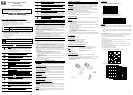
In the case of four readout areas
The designated areas are read out in order of
address from start (X1, Y1) to the end (X8, Y8).
(1)
(2)
(3)
(4)
(5)
(6)
(7)
(X1,Y1)
(X2,Y2)
In the case of only one readout area
A readout area can be designated by the start
address (X1, Y1) and the end address (X2, Y2).
The camera can read out the user-defined area
through this function.
The each address is designated by the start
address and lengths (pixel numbers) of “X” and
“Y” directions.
A-block
B-block
(1)
(2)
(3)
(4)
(5)
(6)
(7)
(8)
(9)
(10)
(11)
(12)
(13)
(14)
(X1,Y1)
(X2,Y2)
(X3,Y3)
(X4,Y4)
In the case of more than two readout areas
The area designated by the start address (X1, Y1)
and the end address (X2, Y2) is read out first
(A-block in the left figure).
After reading out of A-block, the next area
designated by (X3, Y3) and (X4, Y4) is read out
(B-block in the left figure)
A-block
B-block
(1)
(2)
(3)
(4)
(5)
(6)
(7)
(9)
(11)
(13)
(15)
(8)
(10)
(12)
(14)
(16)
(17)
(18)
(19)
(20)
(X1,Y1)
(X2,Y2)
(X3,Y3)
(X4,Y4)
In the case of more than two readout areas and
including the same readout lines with each other
The designated areas are read out in order of
address from the start (X1, Y1) to the end (X4,
Y4).