


D4153660A
3
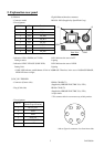
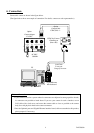
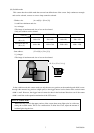
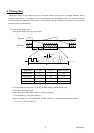
5. Explanation rear panel
(1) Ethernet Gigabit Ethernet Interface connector
- Connector model P65-P01-19V8 (Supplied by SpeedTech Corp.)
- Pin assignment
Pin No. I/O Function
1 I/O BI_DA+
2 I/O BI_DA-
3 I/O BI_DB+
4 I/O BI_DC+
5 I/O BI_DC-
6 I/O BI_DB-
7 I/O BI_DD+
8 I/O BI_DD-
- Indication LED1: GREEN (ACT LED) LED1 indicates the state of ACT.
During transfer: Lighting
- Indication LED2: YELLOW (LINK LED) LED2 indicates the state of LINK.
During Link: Lighting
* LINK LED indicates establishment of Link of 1000BASE. Therefore, in the case of 100BASE/10BASE,
LINK LED does not light.
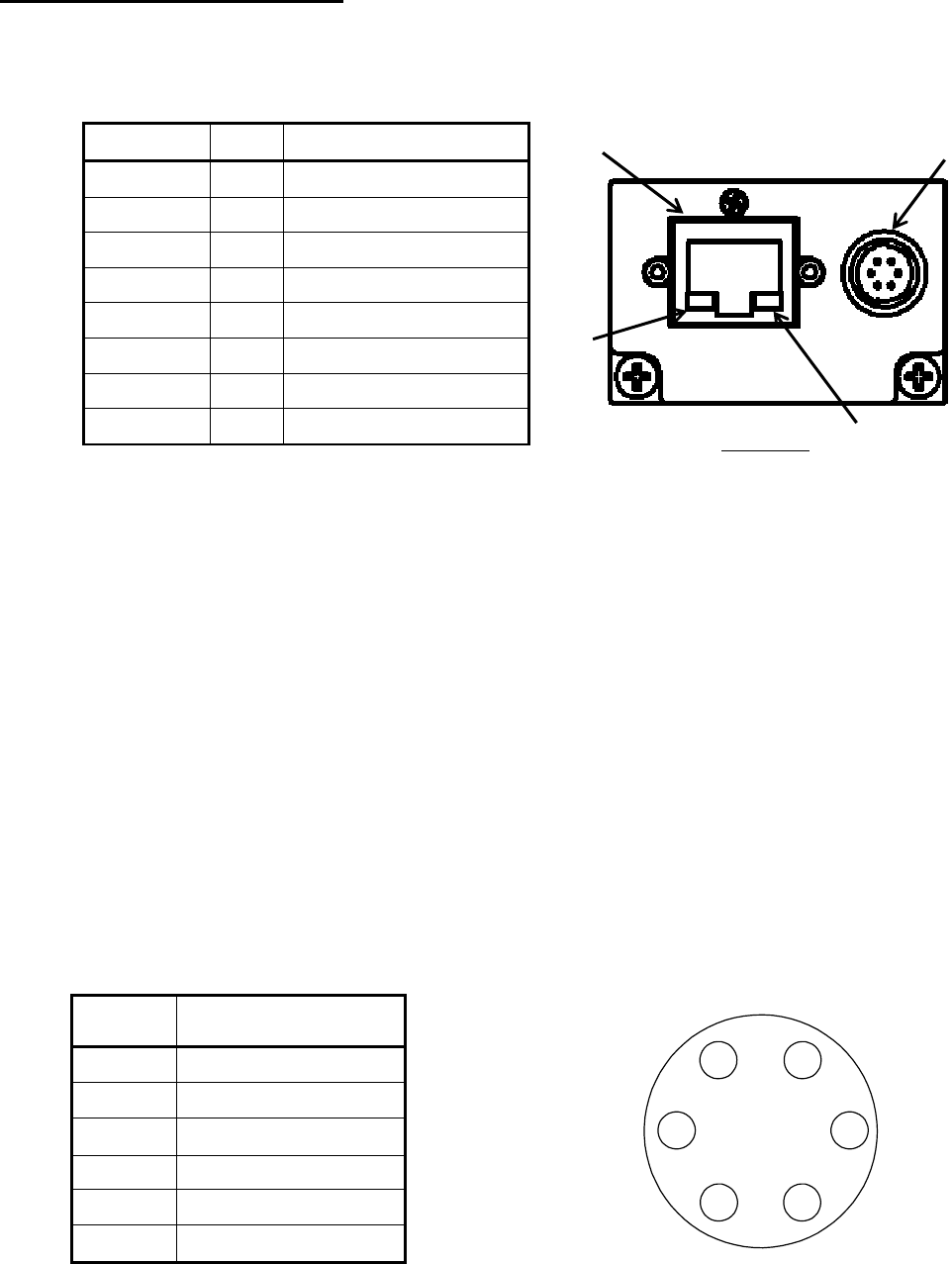
(2) DC_IN / TRIGGER
- Connector (Camera side) HR10A-7R-6PB(73)
(Supplied by HIROSE ELECTRIC CO., LTD.)
- Plug (Cable side) HR10A-7P-6S(73)
(Supplied by HIROSE ELECTRIC CO., LTD.)
or equivalents
* This camera cable is not an accessory of this product.
- Pin assignment
Pin No.
Signal Name
[Standard specification]
1 BUSY_OUT
2 GND
3 GND
4 TRIG_IN
5 EXPOSE_OUT
6 +12V
(2)
(1)
Rear View
LED1
LED2
* Above figure is connector view from insert side.
1 6
2
3 4
5