


- 4 -
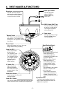
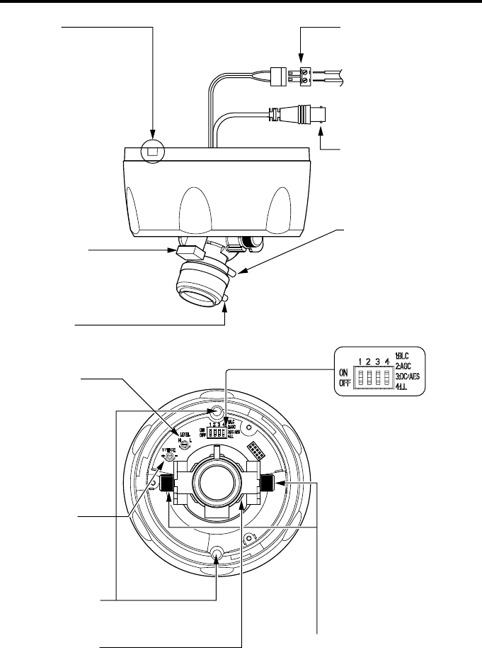
4. PART NAMES & FUNCTIONS :
Knockout
VIDEO Cable (BNC Tap)
Power Input Cable
"Bottom" mark
Focus Lever
Zoom Lever
Lens Iris ADJ
Mode Setting Switch
1:BLC
(
Backlight Compensation Control
)
When switched on, it
automatically adjusts to
compensate for subjects that
are lit from behind.
2:AGC (Auto Gain Control)
When switched on, it
automatically adjusts the
image in relation to the
brightness of the subject.
3:DC/AES
Not available for this camera.
Be sure to switch to ON.
4: LL (Line Lock)
Use this switch to set the
camera synchronization to
internal or line lock. Line
Lock is available with AC24V
only.
Installation Holes
Installs camera to ceiling with
attached screws.
Lens ADJ Screw
Turn the ring-type screw to adjust the lens pan angle.
Fasten and lock it after completing the adjustment.
Tilt ADJ Screws
Turn the screws to adjust the lens tilt
angle. Fasten and lock them after the
adjustment completes.
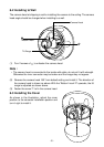
V Phase ADJ
Cut with a knife or scissors
and insert the cables through
the knockout so the cables will
not pinched when installed.
The "Bottom" mark indicates the
lens position. The "Bottom" mark
should be on the top when installing
in a ceiling.
Adjusts the image into focus. Its screw
design allows locking capability.
Use to compensate
for the iris level.
Turn towards L (low)
for a darker picture.
Turn towards H (high)
for a brighter picture.
Optimum value is
adjusted at the
default setting.
Adjusts the phase
difference between
this camera and other
cameras when in Line
Lock mode.
Connect the power
cable to AC24V or
DC12V. (RED:+12,
Black:GND)
Connect the Video Cable to
a monitor or video device.
The image is outputted
when powered on.
Changes the picture range.
Its screw design allows
locking capability.