


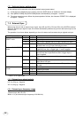
25
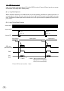
About 1 µs
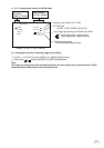
Exposure period*
2
Exposure period*
2
Trigger*
1
Negative polarity mode
Positive polarity mode
RGB data
(video interval image)
(Internal VD)
*
3
FVAL
LVAL,
DVAL
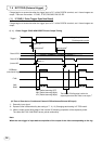
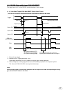
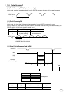
28H (Partial scanning OFF)
38H (Partial scanning 60fps)
47H (Partial scanning 90fps)
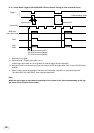
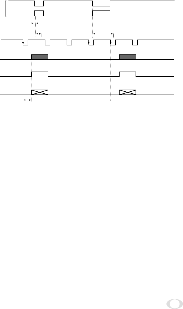
ger, there will be an effect on the video.
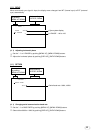
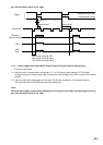
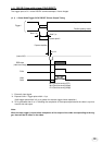
(1. 2) 1 Pulse Trigger SYNC-NON RESET Picture Output Timing (at Time of Internal Sync)
*1: Externally input signal
*2: Exposure time is determined by the setting of "7. 2 (1.3) Changing each setting in E.TRG mode".
As long as there is no external sync input, the internal VD will be output when SJ01 is set to HD/VD output
position.
*3: Video is output at the falling edge of the internal VD following completion of the exposure period.
The video and FVAL/LVAL/DVAL have a paired relationship.
Note:
When the next trigger is input before completion of the output of the video corresponding to the trig-
ger, there will be an effect on the video.