


26
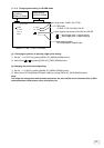
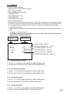
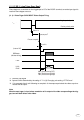
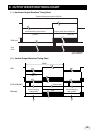
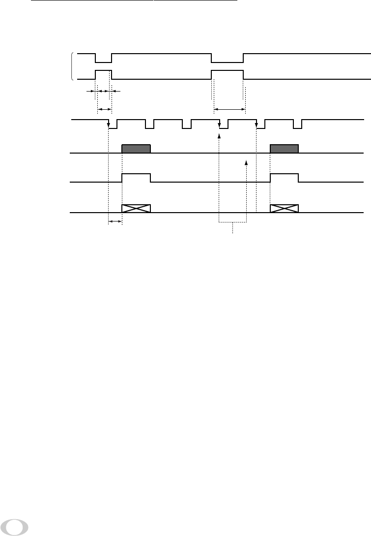
( 3 ) PW SNR (Pulse width trigger SYNC-NON RESET)
The trigger input to CC1 of the DIGITAL terminal develops 1 frame images.
(3. 1) Pulse Width Trigger SYNC-NON RESET Picture Output Timing
*1: Externally input signal
*2: Exposure time = Trigger pulse width + 6 µs
(Valid trigger pulse width is 2 µs or greater for external trigger shutter operation.)
*3: Video is output at the falling edge of the internal VD following completion of the exposure period.
The video and FVAL/LVAL/DVAL have a paired relationship.
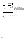
Note:
When the next trigger is input before completion of the output of the video corresponding to the trig-
ger, there will be an effect on the video.
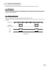
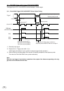
Exposure period*
2
Tr igger*
1
Exposure period*
2
The internal VD falling edge is within the
exposure period and thus video is not output.*
3
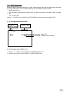
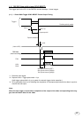
Negative polarity mode
Positive polarity mode
About 7 µsAbout 1 µs
(Internal VD)
RGB data
(video interval image)
FVAL
LVAL,
DVAL
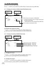
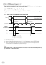
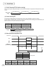
58H (
Partial scanning OFF
)
56H (
Partial scanning
30fps)
78H (
Partial scanning
40fps)