-
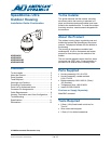
IMPORTANT! This housing meets IP66/Nema 4 ratings
provided it is used with a properly installed ROENDC End
Cap Assembly and one of the following mounts: RHOTR
Over-the-Roof Mount, RHOSW Short Wall Mount, or
RHOLW Long Wall Mount.
ADSDUHOC, ADSDUHOS, ADSDUHOVRC, ADSDUHOVRS
SpeedDome
®
Ultra Outdoor Housing Installation Guide
Before performing these steps, read additional
information attached for important details and
warnings!
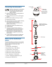
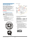
A
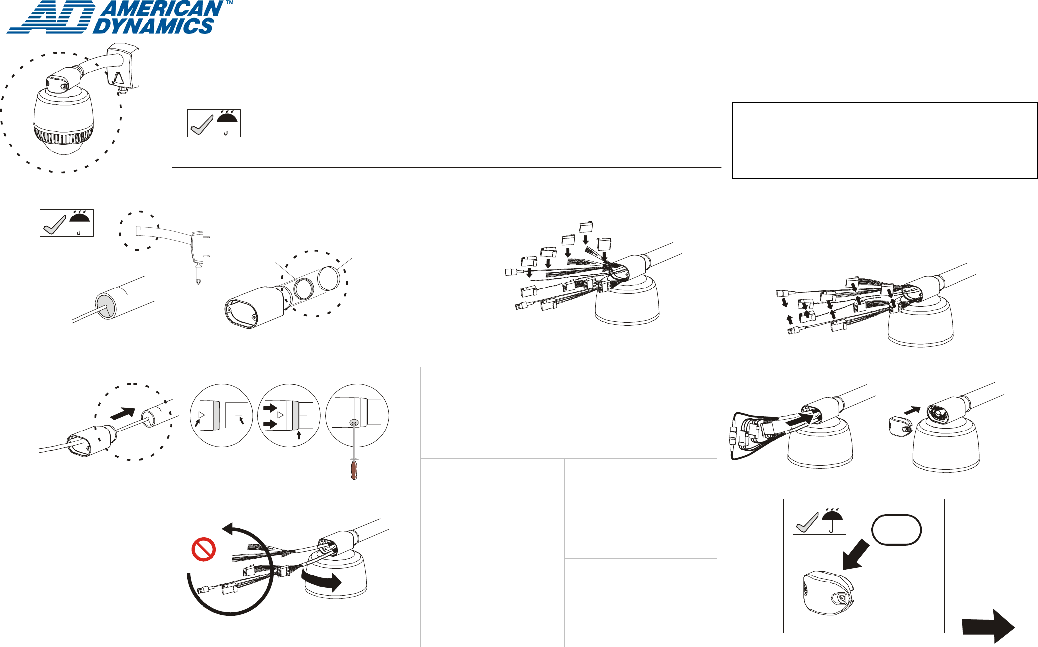
t end of pipe.
Ensure black foam plug is around
cable and press-fit into pipe.
Ensure seal and sleeve are
properly set.
See A, B, C.
Line up.
Push to line and
maintain
compression.
Tighten.
Thread cables through end
cap assembly and attach
housing to mounting
structure.
Keep cables from
twisting while turning
housing.
Turn until no threads
are exposed.
A
ttach cable
connectors.
Make connections,
insert cables into end
cap assembly, and
attach cover.
Check o-ring is
properly set.
Page 1 of 12 8200-0492-02, Rev. C
Seal
Sleeve
1
B
A
2
A
3
B
C
= Step Prevents
Water Intrusion.
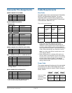
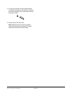
Green 3-Pin Connector (Power)
Pin 1 - Black (24Vac)
Pin 2 - Red (Common)
Pin 3 - White (24Vac)
Green 2-Pin Connector (Twisted Pair Video)
Pin 1 - + (video high)
Pin 2 - – (video ground)
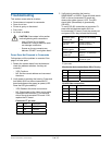
Gray 5-Pin Connector
(Relay)
Pin 1 - Blue (NC)*
Pin 2 - Purple (Common)*
Pin 3 - Gray (NO)*
Pin 4 - White/Red (Alarm Return)
Pin 5 - White/Black (Alarm 1)
* Relay contact not to exceed 1A @
30Vdc or 0.3A @ 125Vac.
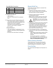
Black Connector (Data)
Manchester
Pin 1-4 - Not used
Pin 5 - White/Orange (Manchester W)
Pin 6 - White/Yellow (Manchester B)
RS-422
Pin 1 – Orange (Rx +)
Pin 2 – Green (Rx –)
Pin 3 – Yellow (Tx +)
Pin 4 – Brown (Tx –)
Pins 5-6 - Not used
SensorNet
Pin 1-4 - Not used
Pin 5 - White/Orange (SensorNet Hi)
Pin 6 - White/Yellow (SensorNet Lo)
Blue 4-Pin Connector
(Alarm)
Pin 1 - White/Blue (Alarm 2)
Pin 2 - White/Brown (Alarm 3)
Pin 3 - White/Purple (Alarm 4)
Pin 4 - White/Red (Alarm Return)


