


take a closer look
1
This distance is for the AD-UTC data only. See cable manufacturers specifications for video
capabilities.
On-screen text supports six languages: English, French,
Italian, Spanish, German and Portuguese.
Password protection prevents unauthorized use of the
configuration utility.
The dome incorporates an innovative twist lock release
from the mounting base for easy installation and servicing.
The fully isolated power supply helps eliminate ground
loops.
Users can set line-lock on or off. Line-lock is enabled to
help prevent vertical rolling in multi-camera applications.
Vertical sync phase adjustment is provided to help
compensate for different phases of power when
line-lock is enabled, making it ideal for single and
multi-phase power installations.
Sensing of 50/60 Hz lines is automatic and does not
require manual adjustment.
Surge protection is provided for video, code, alarms
and power connections.
Daisy chain configuration of control wiring is enabled:
- For RS-422: 10 domes at a maximum distance of 1
km (3000 ft) on two 22 AWG shielded twisted pairs
(STP)
- For SensorNet: 32 devices at a maximum distance
of 1 km (3000 ft) on one 22 AWG unshielded twisted
pair (UTP)
- For Manchester: 3 domes at a maximum distance of
1500 m (5000 ft) on one 18 AWG shielded
twisted pair (STP)
- For AD-UTC
1
: Maximum distance per dome is 700 m
(2300 ft) on 20 AWG RG59U cable
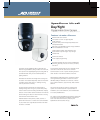
The features of the SpeedDome Ultra VII with EIS
can be extended to outdoor environments via the
SpeedDome Ultra Outdoor Housing. The outdoor
housing, designed especially for the SpeedDome Ultra’s
small, unobtrusive size, makes it the perfect
protection for the dome. The housing now features a
reinforced outdoor housing as standard and a heavy
duty vandal resistant housing kit option.
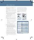
Two Mounting Base Options
The housing/eyeball assembly twist locks into both
mounting bases. The I/O board base connects the
housing/eyeball assembly in one step. Power, communication
and video cables (or composite cable) are connected one
time to an I/O PC board in the mounting base, so the
assembly is simply twist locked onto the base. Service
and maintenance are easy and can be accomplished
without a ladder or lift via the installation/removal tool. The
I/O board mounting base supports four alarm inputs and
four alarm outputs as well as power and communication
LEDs. The standard base connects the housing/eyeball
assembly in two steps. First, power, communication and
video cables (or composite cable) are inserted through the
base and attached to the assembly. Then the assembly
is connected to the base. The standard mounting base
supports one alarm input and one alarm output. The
installation/removal tool cannot be used to install this
configuration.
with I/O Board
Mounting Base
with Flying Lead
Mounting Base
(Pigtail)
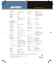
NUMBER OF PRESETS
Controller or
Matrix Switcher Protocol Number of Presets
ADTT16E SensorNet 96
RS-422
2
4
MegaPower LT AD-UTC 96
SensorNet 96
AD2150 Manchester 64
RS-422
3
16
MegaPower 48 and SensorNet 96
MegaPower 48 Plus Manchester 64
RS-422 96
VM96 SensorNet Unlimited
RS-422 Unlimited
MegaPower 168 SensorNet 64
Manchester 64
RS-422 64
RS-422
3
16
MegaPower 1024 Manchester
4
64
RS-422
3
16
Third party interfaces RS-485 96
2
Using SensorNet-to-RS-422 Converter (model number RCSN422)
3
Using RS-422 Code Distributor (model number AD2083-02B)
4
Using Manchester Code Distributor (model number AD2091)