


AXIS 215 PTZ Installation Guide Page 15
ENGLISH
ENGLISH
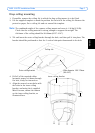
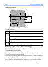
Unit connectors
Network connector - RJ-45 Ethernet connector. Using shielded cables is recommended.
Power connector - DC connector 12V DC
±5%, max 14.5W. See product label for ±
connection.
Audio in - 3.5mm input for a mono microphone, or a line-in mono signal (left channel is
used from a stereo signal).
Audio out - Audio output (line level) that can be connected to a public address (PA) system
or an active speaker with a built-in amplifier. A pair of headphones can also be attached. A
stereo connector must be used for the audio out.
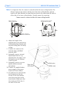
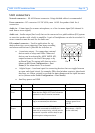
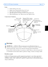
I/O terminal connector - Used in applications for e.g.
motion detection, event triggering, time lapse recording
and alarm notifications. It provides the interface to:
• 1 transistor output - For connecting external
devices such as relays and LEDs. Connected
devices can be activated by AXIS VAPIX API,
output buttons on the Live View page or by
an Event Type. The output will show as active
(shown under Event Configuration > Port
Status) if the alarm device is activated.
• 1 digital input - An alarm input for connecting devices that can toggle between
an open and closed circuit, for example: PIRs, door/window contacts, glass break
detectors, etc. When a signal is received the state changes and the input becomes
active (shown under Event Configuration > Port Status).
• Auxiliary power and GND
Function Pin number Notes Specifications
GND 1 Ground
12V DC
Power
2 Can be used to power auxiliary equipment.
Note that the AXIS 215 PTZ itself cannot be
powered via the I/O terminal connector.
Max load = 100mA
Digital Input 3 Connect to GND to activate, or leave float-
ing (or unconnected) to deactivate.
Must not be exposed to
voltages greater than
12V DC
Transistor
Output
4 Uses an open-collector NPN transistor with
the emitter connected to the GND pin. If
used with an external relay, a diode must be
connected in parallel with the load, for pro-
tection against voltage transients.
Max load = 100mA
Max voltage = 24V DC
(to the transistor)
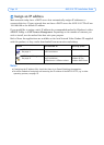
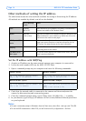
Pin 4
Pin 3
Pin 2
Pin 1