


46
AXIS 221 - Unit Connectors
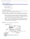
Unit Connectors
This section describes the following:
• The I/O Terminal connector
• Power connections
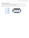
• The RS-232 D-Sub connector
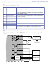
I/O Terminal connector
The 10-pin I/O terminal connector provides the interface to a solid state relay output, two
digital photo-coupled inputs, RS-485, GND and auxiliary power.
The terminal connector is used in applications for e.g. motion detection, event triggering,
time lapse recording, alarm notification via e-mail, image storage to FTP locations, etc.
• Input - Used for connecting external alarm devices and triggering images for
specific alarm-based events. The input is typically connected to a motion detector
or any other external security device, and images can be uploaded whenever the
detector is activated. Maximum 18VDC is allowed on the input.
• Output - This can drive a maximum load of 50VDC or 35VAC at 100mA directly
or heavier loads by connecting additional relay circuitry. If the output is used
with an external relay, a diode must be connected in parallel with the load for
protection against any voltage transients.
Caution!
Connecting AC to the inputs/outputs will damage the unit.
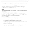
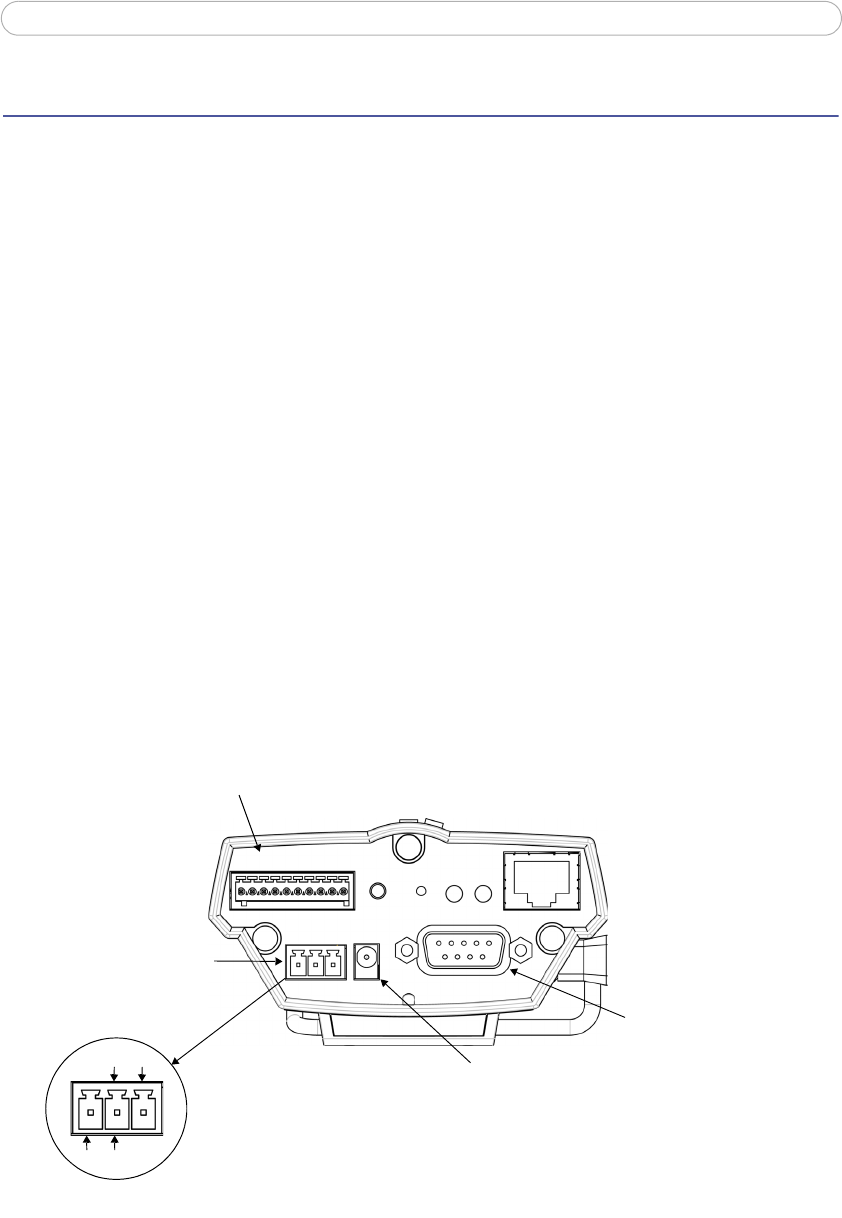
10-pin I/O Terminal connector
12345678910
connector
Power
block
connector
Power adapter
RS-232 connector
(including RS-485)
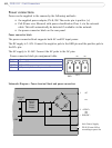
AC AC
GND DC+
Connect DC power (7-24V) on pins 1 and 2.
Connect AC power (10-24V) on pins 2 and 3.