


AXIS M3203-V Network Camera
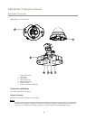
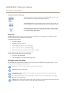
Hardware Overview
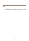
Hardware Overview
2
1
3
4 5
6
7
1
Status indicator LED
2
Cover plates
3
Control button
4
Power indicator LED
5
Network indicator LED
6
Network connector
7
Product ID and Serial number (S/N)
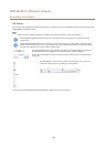
Connectors and Buttons
For technical specications, see page 51.
Network Connector
RJ45 Ethernet connector with Power over Ethernet (PoE).
NONO
NO
TICETICE
TICE
The product shall be connected using a shielded network cable (STP). All cables connecting the product to the network shall
be intended for their specic use. Make sure that the network devices are installed in accordance with the manufacturer’s
instructions. For information about regulatory requirements, see Electromagnetic Compatibility (EMC) on page 2 .
5