


AXIS T95A00/T95A10 Dome Housing Page 7
ENGLISH
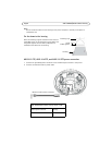
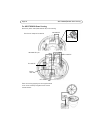
AXIS 231D+/232D+ and AXIS 233D power connection
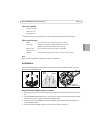
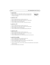
1. Unplug the connector from the 12 VDC power supply opposite the bracket opening as shown in
the illustration below.
2. Remove the green connector from the cables.
3. Connect the cables to the camera power input as described below:
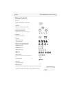
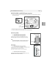
AXIS 231D+/232D+
• AXIS T95A00 Dome Housing (24V DC)
• AXIS T95A10 Dome Housing (24V AC)
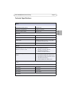
Connect the brown cable to the 24V AC/DC pins on the
AXIS 231D+/232D+ connection module (see illustration).
Note:
The AXIS 231D+/232D+ connection module contains a
rectifier so the cables can be connected either way.
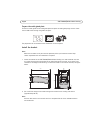
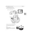
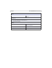
AXIS 233D
• AXIS T95A00 Dome Housing (24V DC)
Connect the brown cable to the GND/DC- and AC/DC+ pins on
the AXIS 233D connector (See illustration).
Be careful to connect (+) and (-) on the correct pins.
• AXIS T95A10 Dome Housing (24V AC)
Connect the brown cable to the AC and AC/DC+ pins on the
AXIS 233D connector (See illustration).
24V
~
+
~
-
12 VDC
power supply
Brown cable
AXIS 231D+/ 232D+
24V AC/DC
Connection module
AXIS 233D
Connector
AC
AC/DC+
GND/DC-
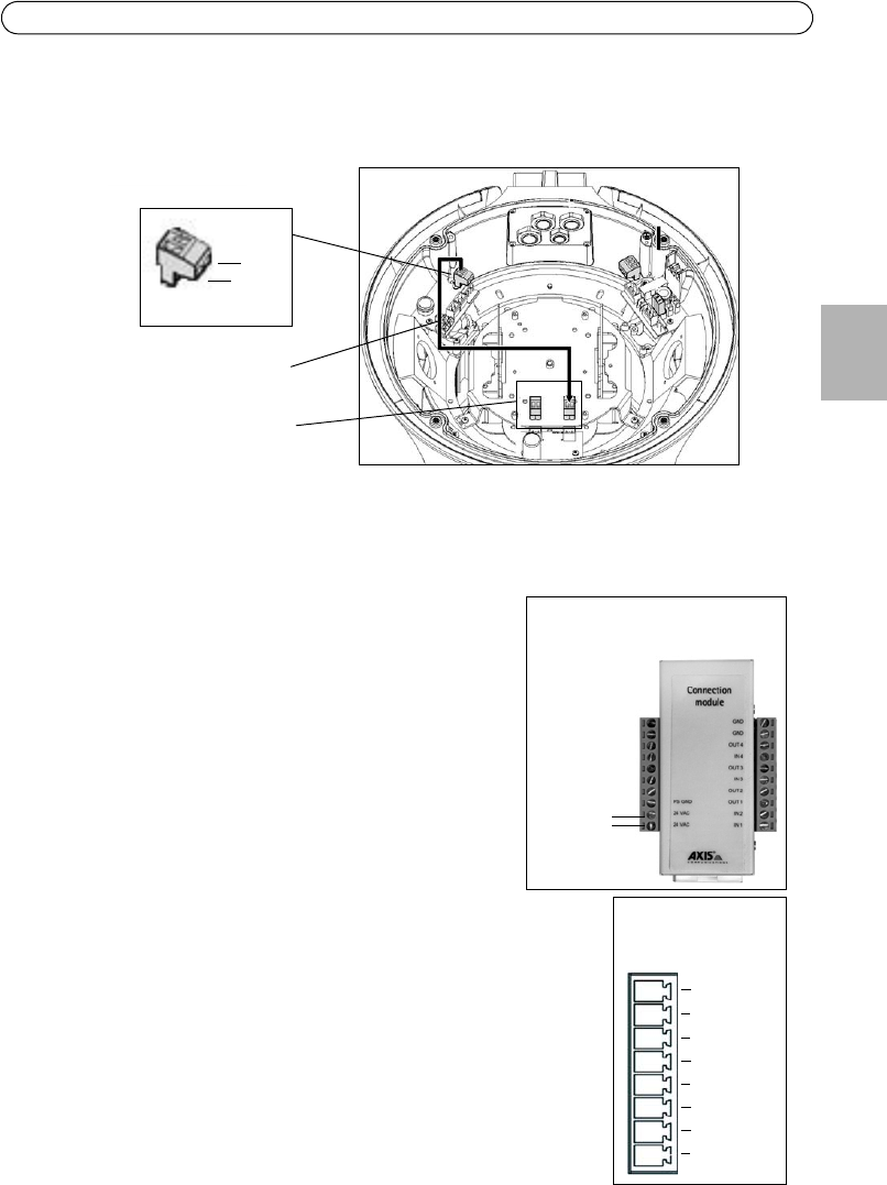
12V out
GND
Line out
GND
Line/Mic in