


AXIS M10 Series Page 5
ENGLISH
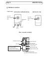
Unit connectors
Network connector - RJ-45 Ethernet connector; shielded cables
recommended.
Power connector - Mini DC connector 5.0-5.1V DC, Max 1.5A.
Center pin +.
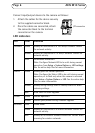
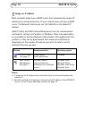
I/O terminal connector (AXIS M1054 only)
The 4-pin I/O terminal connector provides the interface to 1 transistor
output, 1 digital input, auxiliary power, GND.
The terminal connector is used in applications for motion detection,
event triggering, alarm notification via email, and image storage to FTP
locations.
• Input - for connecting a push button, for example. If the push button
is pressed, the state changes and the input becomes active (shown
under Events > Port Status).
• Output - connects an alarm device that can be activated by Output
buttons on the Live View page, or by an Event Type. The output shows
as active (Events > Port Status) if the alarm device is activated.
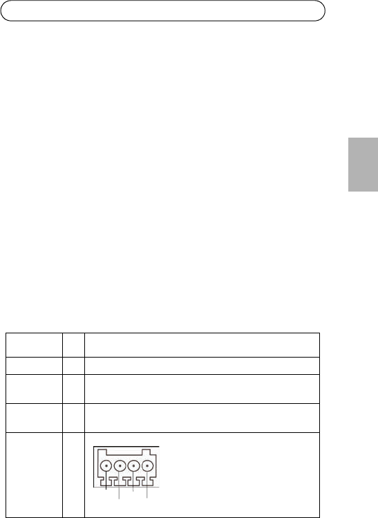
Function Pin Notes
GND 1 Ground
3.3V DC
Power
2 Can be used to power auxiliary equipment.
Note: This pin can only be used as power out.
Digital Input 3 Connect to GND to activate, or leave floating (or
unconnected) to deactivate.
Transistor
Output
4 Uses an open-drain NFET transistor
with the source connected to GND. If
used with an external relay, a
diode must be connected in parallel
with the load, for protection against
voltage transients.
Pin 3
Pin 4
Pin 2
Pin 1