


AXIS M1114
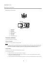
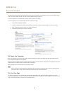
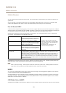
Hardware Overview
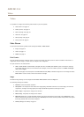
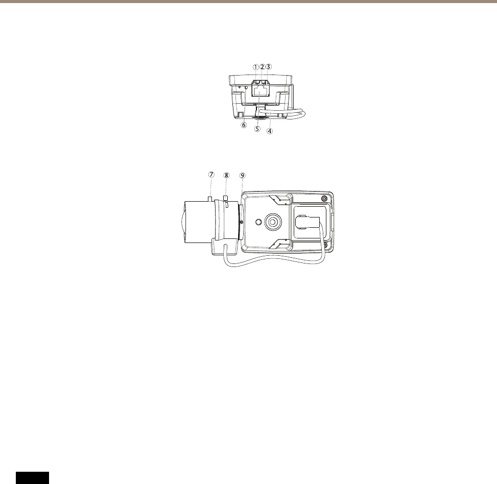
Hardware Overview
4
5
7
8
6
1
2
3
9
1.
Network LED
2.
Status LED
3.
Power LED
4.
Iris connector
5.
Network connector
6.
Control button
7.
Zoom puller
8.
Focus puller
9.
Screw holding CS ring
Connectors and Buttons
For technical specications, see page 52.
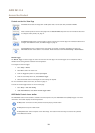
Network Connector
RJ45 Ethernet connector with Power over Ethernet (PoE).
NONO
NO
TICETICE
TICE
The product shall be connected using a shielded network cable (STP). All cables connecting the product to the network shall
be intended for their specic use. Make sure that the network devices are installed in accordance with the manufacturer’s
instructions. For information about regulatory requirements, see Electromagnetic Compatibility (EMC) on page 2 .
Control Button
For location of the control button, see Hardware Overview on page 6 .
The control button is used for:
• Resetting the product to factory default settings. See page 47.
• Connecting to an AXIS Video Hosting System service. See page 41. To connect, press and hold the button for about 3
seconds until the Status LED ashes green.
• Connecting to AXIS Internet Dynamic DNS Service. See page 41. To connect, press and hold the button for about 3 seconds.
6