


AXIS M3024–LVE Network Camera
Technical Specications
Function/group
Item
Specications
Weight
820 g (12.8 lb.)
Included
accessories
Drill hole template, Installation Guide, Installation and Management Software CD,
Windows decoder 1-user license, Torx L-key, terminal block connector
Video
management
software
AXIS Camera Companion (included), AXIS Camera Station and video management
software from Axis’ Application Development Partners (not included). See
www.axis.com/products/video/software
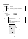
Connectors
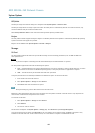
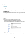
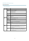
I/O connector
4–pin terminal block for:
• Auxiliary power (DC output)
• Digital Input
• Digital Output
• 0 V DC (-)
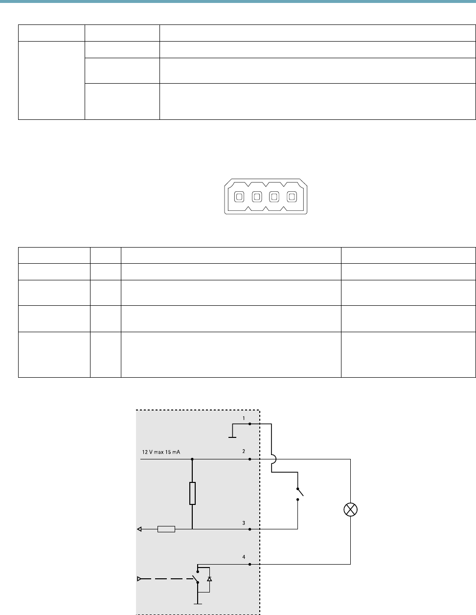
Function Pin Notes
Specications
0 V DC (-)
1
DC output
2
Can be used to power auxiliary equipment.
Note: This pin can only be used as power out.
12 V DC
Max load = 15 mA
Digital Input
3
Connect to pin 1 to activate, or leave oating (unconnected)
to deactivate.
0 to max 30 V DC
Digital Output
4
Connected to pin 1 when activated, oating (unconnected)
when deactivated. If used with an inductive load, e.g. a relay,
a diode must be connected in parallel with the load, for
protection against voltage transients.
0 to max 30 V DC, open drain,
100 mA
12 V max 15 mA
1
2
3
4
54