


AXIS M3027-PVE Fixed Dome Network Camera
Technical Specifications
Connectors
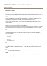
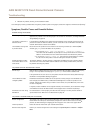
I/O Connector
4–pin terminal block
1
2 3 4
For an example diagram, see Connection Diagrams on page 64.
Function Pin Notes
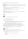
Specications
0 V DC (-)
1
0 V DC
DC output
2
Can be used to power auxiliary equipment.
Note: This pin can only be used as power out.
12 V DC
Max load = 15 mA
Digital Input
3
Connect to pin 1 to activate, or leave oating (unconnected)
to deactivate.
0 to max 30 V DC
Digital Output
4
Connected to pin 1 when activated, oating (unconnected)
when deactivated. If used with an inductive load, e.g. a relay,
a diode must be connected in parallel with the load, for
protection against voltage transients.
0 to max 30 V DC, open drain,
100 mA
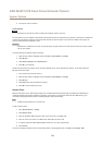
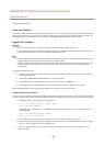
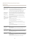
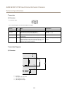
Connection Diagrams
I/O Connector
1
2
3
4
1
0 V DC (-)
2
DC output 12 V, max 15 mA
3
I/O congured as input
4
I/O congured as output
64