


AXIS P1214–E Network Camera
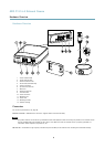
Hardware Overview
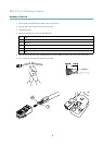
Hardware Overview
10
11
98
7
321
654
12
13
14
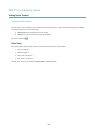
1
Power indicator LED
2
Status indicator LED
3
Network indicator LED
4
SD card slot (microSD card)
5
Camera connector
6
I/O terminal connector
7
Main unit
8
Network connector
9
Control button
10
Power connector
11
Mounting rail
12
Sensor unit
13
Mounting bracket
14
Outdoor housing
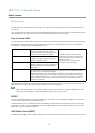
Connectors
For technical specications, see page 45.
Network connector - RJ45 Ethernet connector. Supports Power over Ethernet (PoE).
NOTICENOTICE
NOTICE
The product shall be connected using a shielded network cable (STP). All cables connecting the product to the network switch
shall be shielded (STP) and intended for their specic use. Make sure that the network switch is properly grounded. For
information about regulatory requirements, see .
SD card slot - A standard or high-capacity microSD card (not included) can be used for local recording with removable storage.
4