


AXIS P1224–E Network Camera
Hardware Overview
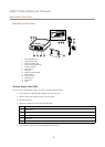
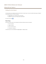
Hardware Overview
10
11
98
7
321
654
12
13
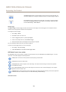
1
Power indicator LED
2
Status indicator LED
3
Network indicator LED
4
SD card slot (microSD card)
5
Camera connector
6
I/O connector
7
Main unit
8
Network connector (PoE)
9
Control button
10
Power connector
11
Mounting rail
12
Sensor unit
13
Cover
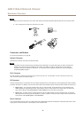
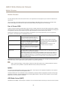
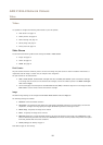
Shorten Sensor Unit Cable
The sensor unit is delivered with a cable. To shorten the cable follow these steps:
1. Cut the cable to the desired length. Measure from the sensor unit.
2. Strip the plastic outer coating from the end of the cable.
3. Peel back the shield.
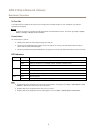
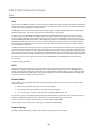
4. Flatten the colored wires in the order described below.
1
Brown
2
White/brown
3
Not used
4
Not used
5
White/blue
6
Blue
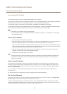
5. Insert the wires all the way into a shielded 6P6C RJ12 connector.
5