


AXIS P13-E Network Camera Series Installation Guide Page 11
ENGLISH
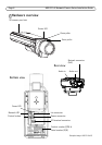
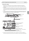
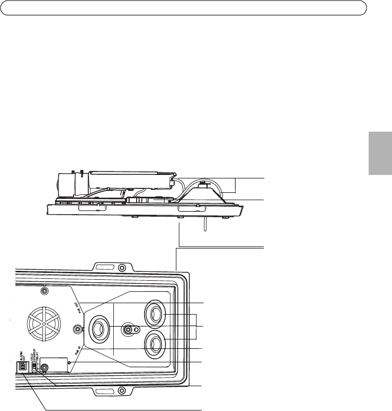
Connect the cables
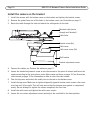
1. Optionally insert an SD memory card (not included) into the SDHC (Secure Digital High
Capacity) card slot. A standard or high capacity SD card is required to store images locally in
the camera.
2. Optionally connect external input/output devices. See page 23 for information on the terminal
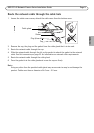
connector pins. Prepare the cables with gaskets, see Route the network cable through the cable
hole, on page 9, and route the cables through the cable holes into the bottom cover and to the
camera.
3. Connect the camera to the network using a shielded network cable. Connect the network cable
to the network connector on the bottom. The network cable and the I/O cable between the
bottom cover and the camera are already connected at delivery
4. Check that the indicator LEDs indicate the correct conditions. See the table on page 25 for
further details. Note that the Status LED can be configured to be unlit during normal operation.
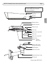
Cable holes
Network connector (PoE IN)
Alarm output
Cold Startup Delay switch
LED indicator
(enabling not required - see text below)
Network connector (PoE OUT,
connected at delivery)
Bottom cover
I/O cable
Network cables
(connected at delivery)