


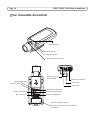

AXIS P1353/P1354 Installation Guide Page 11
ENGLISH
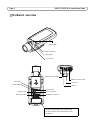
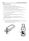
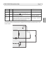
The following connection diagram gives an example of how to connect an auxiliary device to the
network camera.
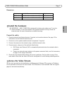
Function Pin Notes Specifications
GND 1 Ground
3.3 V DC
Power
2 Can be used to power auxiliary equipment.
Note: This pin can only
be used as power out.
Max load = 50 mA
Digital
Input
3 Connect to GND to activate, or leave floating
(unconnected) to deactivate.
Min. input = -40 V DC
Max. input= +40 V DC
Digital
Output
4 Uses an open-drain NFET transistor with the source
connected to GND. If used with an external relay, a
diode must be connected in parallel with the load,
for protection against voltage transients.
Max. load =100 mA
Max. voltage = + 40 V DC
3.3 V max 50 mA
1
2
3
4