


AXIS P3384–V Fixed Dome Network Camera
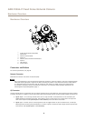
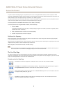
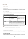
Hardware Overview
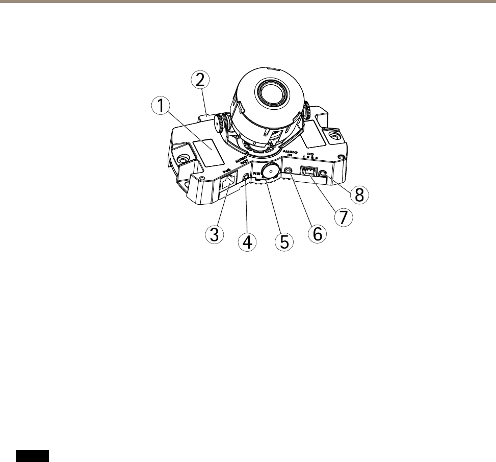
Hardware Overview
2
1
3
4
5
6
7
8
1
Product ID and Serial number (S/N)
2
SD card slot
3
Network connector (PoE)
4
Audio out
5
Network, Status and Power LED indicators
6
Audio in
7
I/O connector
8
Control button
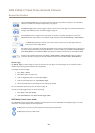
Connectors and Buttons
For technical specications, see page 62.
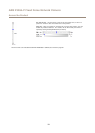
Network Connector
RJ45 Ethernet connector with Power over Ethernet (PoE).
NONO
NO
TICETICE
TICE
Due to local regulations or the environmental and electrical conditions in which the product is to be used, a shielded network
cable (STP) may be appropriate or required. All cables connecting the product to the network and that are routed outdoors
or in demanding electrical environments shall be intended for their specic use. Make sure that the network devices
are installed in accordance with the manufacturer’s instructions. For information about regulatory requirements, see
Electromagnetic Compatibility (EMC) on page 2 .
I/O Connector
Use with external devices in combination with, for example, tampering alarms, motion detection, event triggering, time lapse recording
and alarm notications. In addition to the 0 V DC reference point and power (DC output), the I/O connector provides the interface to:
• Digital output – For connecting external devices such as relays and LEDs. Connected devices can be activated by the
VAPIX® Application Programming Interface, output buttons on the Live View page or by an Action Rule. The output will
show as active (shown under System Options > Ports & Devices) if the alarm device is activated.
• Digital input – An alarm input for connecting devices that can toggle between an open and closed circuit, for example:
PIRs, door/window contacts, glass break detectors, etc. When a signal is received the state changes and the input becomes
active (shown under System Options > Ports & Devices).
6