


AXIS T90B Series
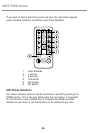
Volt-free input:
Non polarity sensitive
Short circuit = Light on
TTL input:
Orange = TTL +ve
Purple = TTL -ve (GND)
0 V = Light on
3 V = Light off
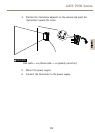
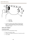
The telemetry input wires (orange and purple) are soldered together
when shipped from the factory to simulate a volt-free input so that the
illuminator automatically turns on and off via the photocell. Any remote
input or switch should be connected to these wires. Snip the end of the
cable and separate the cables to use with remote switch or input.
Under normal operating conditions, a telemetry input will activate the unit
only at night provided that the photocell detects low light conditions.
However, if the photocell is disabled, a telemetry input will activate the
unit regardless of ambient light conditions.
The mode of operation is selected by using the remote control.
The remote input can be used in conjunction with the illuminator in the
following ways:
1. TEL — see page 24
2. DIM — see page 25
3. TEL + TIMER — see page 25
Telemetry - TEL
Press the TEL button if the illuminator is to be turned on and off using
a remote switch or input.
The TEL input can be used in various ways:
24