


AXIS T95A00/T95A10 Dome Housing Page 15
ENGLISH
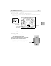
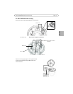
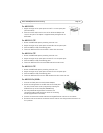
For AXIS 233D
1. Adjust the height of the spacer plates to hole F+1 on the spacer plate
(See illustration).
2. Place the camera within the four ears of the Universal Adaptor and
screw it onto place. The adaptor is supplied already configured for the
AXIS 233D.
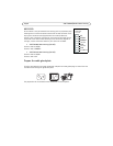
For AXIS 213 PTZ
1. Detach the AXIS 233D plate by removing the three nuts.
2. Adjust the height of the spacer plates to holes B+2 on the spacer plate.
3. Place the AXIS 213 PTZ on the Moving plate.
4. Fasten the AXIS 213 PTZ to the two PM 11 holes with two screws.
For AXIS 214 PTZ
1. Detach the AXIS 233D plate by removing the three nuts.
2. Adjust the height of the spacer plates to holes E+1 on the spacer plate.
3. Place the AXIS 214 PTZ on the Moving plate.
4. Fasten the AXIS 214 PTZ to the three PM5 holes with three screws.
For AXIS 215 PTZ
1. Detach the AXIS 233D plate by removing the three nuts.
2. Adjust the height of the spacer plates to holes E+2 on the spacer plate.
3. Place the AXIS 215 PTZ on the Moving plate.
4. Fasten the AXIS 215 PTZ to the four PM 10 holes with four screws and nuts.
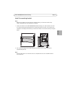
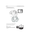
For AXIS 231D+/232D+
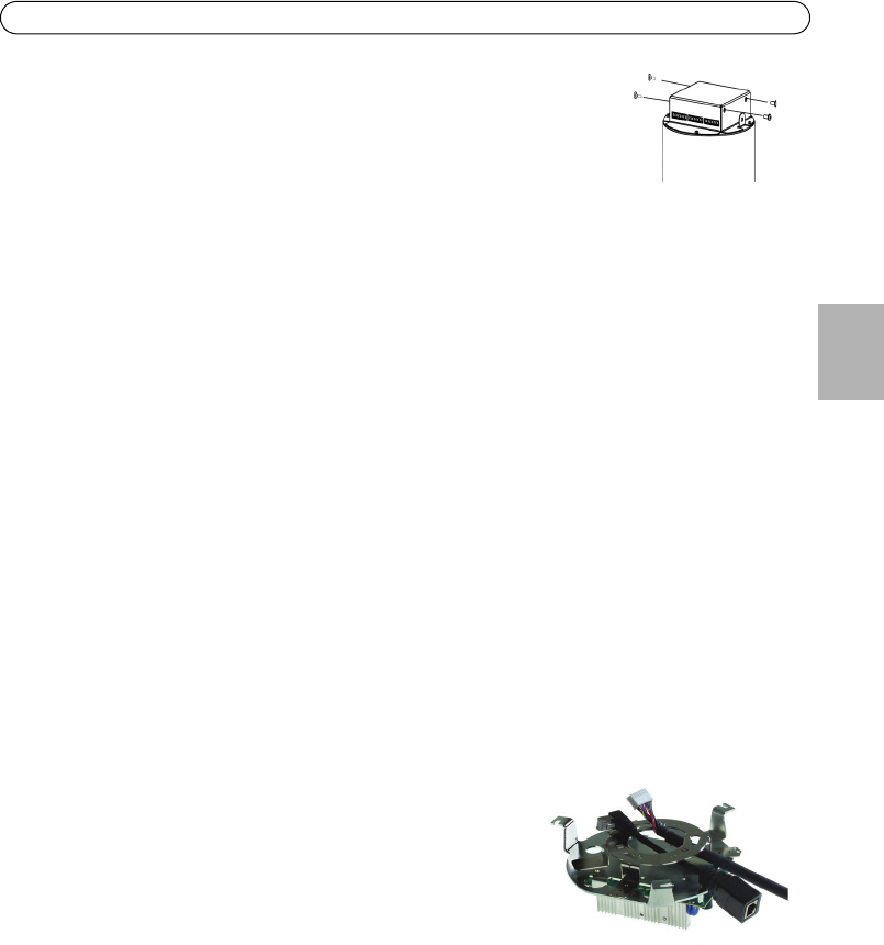
1. Unscrew the fixed plate from the Universal Adaptor.
2. Attach the ceiling bracket to the PF2 holes on the fixed plate.
You may find this easier to do by temporarily removing the
PCB from the top of the fixed plate (T95A00 only).
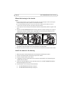
3. Pull the provided 90° angle Ethernet connector and
connection module cable through the center of the ceiling
bracket (supplied with the camera).
4. Connect the connection module cable and the angled Ethernet connector to the camera.
5. Guide the studs on the base of the camera into the holes on the ceiling bracket and rotate it to
fix in position.