


EN
|
3
Bosch Security Systems | 28 July 2004
LTC 9312 Series | Instruction Manual | Unpacking
1UNPACKING
This mechanical equipment should be unpacked and
handled carefully.
Check for the following items:
Qty. Item
1LTC 9312/00
1 Clear dome
2 Support channels
1 Black opaque liner
1FM2 camera bracket assembly
1 Black dust cover
If an item appears to have been damaged in shipment,
replace it properly in its carton and notify the shipper.
If any items are missing, notify your Bosch Security
Systems Inc. Sales Representative or Customer Service.
The shipping carton is the safest container in which the
unit may be transported. Save it for possible future use.
2SERVICE
If the unit ever needs repair service, the customer
should contact the nearest Bosch Security Systems, Inc.
Service Center for return authorization and shipping
instructions.
Service Centers
USA
Phone: 800-366-2283 or 717-735-6638
fax: 800-366-1329 or 717-735-6639
CCTV Spare Parts
Phone: 800-894-5215 or 408-956-3853 or 3854
fax: 408-957-3198
e-mail: BoschCCTVparts@ca.slr.com
Canada
Phone: 514-738-2434
Europe, Middle East & Asia Pacific Region
Phone: 32-1-440-0711
For additional information, see
www
.boschsecuritysystems.com.
3INSTALLATION
1. Remove the contents from the box.
2. Remove the ceiling tile in the desired location.
3. Place the acrylic dome in the chosen location;
the dome will rest on the ceiling grid. (Be sure
the grid is adequately supported.)
4. Using a utility knife or scissors, carefully cut a
hole in the black opaque liner, for the camera
to view through.
NOTE: Smaller cutouts allow more discreet
viewing.
5. Place the black opaque liner into the acrylic
dome and rotate it to the desired viewing
position.
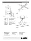
6. Align the long slots of two FM2 camera
bracket arms.
7. Using a carriage bolt, 5/16in. washer, 1/4in.
washer, lockwasher, and hex nut, attach the
bracket arms together loosely. See FIGURE 1.
8. Slide the smaller channel through the slot on
the larger support channel. See FIGURE 2.
Use the 1/4 x 20 bolt supplied to connect the
FM2 to the support channels (via the center
hole in the two channels). BE CAREFUL
WHEN HANDLING THE SUPPORT
CHANNELS; EDGES MAY BE SHARP.
9. Securing tabs are provided to hold the bracket
between the liner. Bend the corresponding tab
with a screwdriver.
10.Connect the camera to the FM2 bracket, and
place the assembly in the dome so the edges
of the bracket rest on the flange of the dome.
11. Tighten all connections and complete wiring
the camera.
12.A tex-wipe is provided to clean the dome.
13. Place the black dust cover over the top of the
dome, so the dust cover is sitting on the
supporting channels.
USE ONLY WITH A CLASS 2 POWER
SUPPLY.
For added flexibility, the camera can be mounted on
either the short or the long side of the bracket arm.