


FLEXIDOME HD VR Installation | en 23
Bosch Security Systems Installation Manual AM18-Q0637 | v1.1 | 2013.08
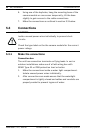
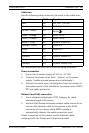
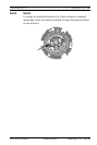
Cable tree
Use the following table to identify the wires in the cable tree:
For connections use wires of at least the same thickness.
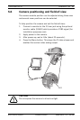
Power connection
1. Use a class 2 power supply 24 VAC or +12 VDC.
2. Connect the power wires (red+ , brown-) to the power
supply. (Isolate unused power wires individually.)
3. Connect the earth wire (yellow/green) from the camera to
the system earth of the installation to ensure correct EMC/
RFI and safety protection.
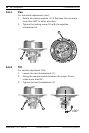
Network (and PoE) connection
1. Use a shielded twisted pair (STP) Category 5e cable,
maximum length 100 meters.
2. Use the RJ45 female-to-female network cable connector to
connect the network cable of the system to the RJ45
connector of the camera (Auto MDIX compliant -
automatically detects the cable connection type).
Power is supplied to the camera via the Ethernet cable,
compliant with the Power-over-Ethernet standard.
Wire color AWG Signal
Red 26 +12 VDC / 24 VAC
Brown 26 GND DC / 24 VAC
Yellow / Green 24
Earth
Black / Orange 28 Alarm Out A
White / Orange 28 Alarm Out B
White / Violet 28 Ground (Alarm In)
Orange / Violet 28 Alarm In 1
Violet 28 Alarm In 2
White 28 Audio In
(Shield) 28 Ground (Audio In)
Black 28 Audio Out
(Shield) 28 Ground (Audio Out)