


Canon BU Series PTZ Camera Systems
Canon BU-Series PTZ Camera Installation and User Guide 341-909 Rev. B Page 4 of 8
INSTALLATION
The instructions below are for wiring and configuring the Canon BU series cameras for installation with Vaddio
joystick controllers. Please refer to the instruction manuals for the BU series cameras for assembling and
configuring the cameras. The Canon BU series cameras are specifically designed for installation on a horizontal
surface with Cat. 5 cable connectivity for RS-232/422 signaling, and coax cabling for video (HD-SDI and composite)
and sync signals.
Before Installing
• Open the box for the camera system, and follow instructions related to camera set-up and configuration. For
the BU-51H, this will include assembling the camera system to the pan/tilt head, as well as connecting power
and control cables between the camera and pan/tilt system that are provided by Canon.
• Locate the camera mounting location paying close attention to camera viewing angles, lighting conditions,
possible line of site obstructions, and checking for in-wall obstructions where the camera is to be mounted.
Pick a mounting location to optimize the performance of the camera.
• An electrical outlet must be located near the Canon BU series PTZ cameras.
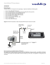
• Pre-wire all cabling as required (see wiring diagram examples).
• For the BU-46H Outdoor PTZ camera, the placement of the camera and any mount fabricated should take into
consideration the environment that it will be placed in (temperature, wind loads, etc.) to assess whether these
conditions conform to the specifications of the BU-46H. The power supply provided with the outdoor camera
must be installed in a weatherproof housing.
MOUNTING INSTRUCTIONS
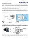
Step 1 (for BU-51H, go from Step 1 to Step 4 on page 6):
After determining the optimum location of the camera system, route the Cat. 5e and Coax cables from the camera
to the Vaddio joystick controller. AC power is required for the BU-51H to operate, so a power outlet needs to be
adjacent to the camera location. While the BU-46H operates on 12 volts DC, the power supply provided with the
camera has terminal leads on it. The maximum distance the power supply can be located from the camera is 70
feet using 12 gauge wire, or 40 feet using 14 gauge wire. The power supply for the BU-46H must be installed in a
weatherproof housing or location.
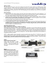
NOTE: Vaddio’s joystick camera controllers transmit and receive data using RS-232. The BU-51H Indoor PTZ
camera utilizes RS-232; however the BU-46H uses RS-422. A protocol converter, included with the Vaddio/Canon
BU-46H system, is required for changing RS-232 to RS-422 in order for the BU-46H to operate. There will be some
additional steps to follow for installation of the BU-46H camera system.
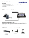
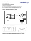
Step 2:
BU-46H Camera System ONLY
Locate both the RJ-45 to DB-9
Adapters and the RS-232 to RS-422
converter. Screw the adapters into
each side of the RS-232 to RS-422
Converter.
Step 3:
BU-46H Camera System ONLY
Locate the 3 foot Cat. 5e patch cable
and connect the RJ-45 to the Control
port on the back of the Vaddio joystick
controller. Connect the other end of
the Cat. 5e cable to the RS-232 side of
the RS-232 to RS-422 converter as
shown.
RS-422