


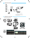

CONNECTION DIAGRAM
LO-77ERK
Extension rings kit
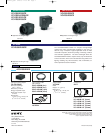
VCL-08YM
VCL-12YM
VCL-16Y-M
VCL-25Y-M
Tripod adaptor
VCT-333I
CCXC-12P02N
Camera cable
C-mount lens
*
1
Only VCL-50Y-M is applicable to the XC-EU50/EU50CE.
*
2
The XC-ES50L/ES50LCE cannot be attached to the VCT-333I.
*
3
HD/VD is not available at C.SYNC.
*
1
VCL-50Y-M
AC
VIDEO OUT
HD/VD
DC
VIDEO OUT
HD/VD*
3
TRIG
WEN
Camera adaptor
DC-700/700CE
(New EIAJ standard 12-pin connector)
CCXC-12P05N
CCXC-12P10N
CCXC-12P25N
XC-ES50/ES50CE
XC-ES50L/ES50LCE*
2
XC-ES51/ES51CE
XC-ES30/ES30CE
XC-EI50/EI50CE
XC-EI30/EI30CE
XC-EU50/EU50CE
Junction box
JB-77
(Trigger input terminal is not available.)
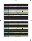
DIMENSIONS & REAR PANEL
Unit: mm
29
12
6.5
C0.5
22
29
29
29
10
6.5
C0.5
C0.5
5.5
32
CCD
XC-ES50L
29 ±0.2 12 ±0.1
6.5
16.5 ±0.2
52.5 ±0.2
30
29 ±0.2
15 ±0.3 (36.6)
28.8 ±0.3 (7.8)
16 ±0.2 (20.8)
8
5.5
φ27.5
4-M3 depth 5
12-pin multi-connector
1
2
4
3
12-pin multi-connector
No. Switch name Factory-setting mode
1 Dip switch 1-4: Shutter speed OFF
Dip switch 5: FRAME/FIELD FRAME
Dip switch 6-8: External trigger
Normal
shutter mode, restart/reset mode
Dip switch 9: Gamma ON/OFF OFF
Dip switch 0: GAIN Manual
2 HD/VD signal input/output switch EXT
3 Control volume for Manual GAIN Twelve o'clock position
4 75 Ω termination switch ON
PIN No. External sync (HD/VD) Internal sync (HD/VD)
1 GND GND
2 +12V DC +12V DC
3 GND GND
4Video output Video output
5 GND GND
6 External HD input Internal HD output
7 External VD input*1 Internal VD output
8 GND GND
9– –
10 WEN output*2 WEN output*2
11 TRIG input TRIG input
12 GND GND
Shutter speed/Mode
setting DIP switch
*1 An input VD signal is required when using restart, reset mode.
*2 WEN output works only when in external trigger shutter mode.
●Factory setting mode of rear panel
XC-ES50/ES50CE/ES51/ES51CE/ES30/ES30CE
XC-EI50/EI50CE/EI30/EI30CE/EU50/EU50CE
XC-ES50L/ES50LCE
SONY47413_XCE 2/28/03 11:07 AM Page 4