


5
4
4
6
7
5
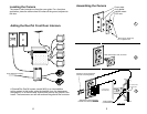
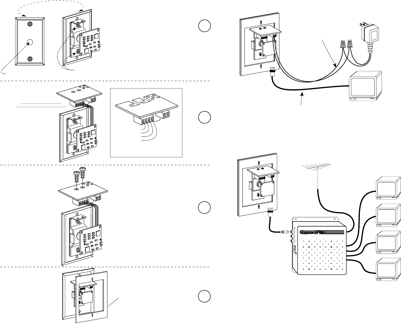
Assembling the Camera (cont.)
CONNECT CAMERA WIRING
TO TERMINAL BLOCK AS SHOWN.
B) TIGHTEN BOTH NUTS TO SECURE ASSEMBLY.
A) ALIGN CAMERA LENS TO HOLE IN OUTSIDE COVER.
ATTACH PC BOARD TO BRACKET
WITH 2 SCREWS, AS SHOWN.
ADD GASKET
On a typical Camera:
Video is Yellow
All other colors are ground.
+Vdc is Red
Video
Video Ground
+Vdc
Ground
BLOW-UP
Monitor
Power cable AWG 26 or larger
RG-59 or RG-6 coax
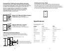
A long cable run (150ft or more) can noticeably
reduce the picture brightness and increases the
possibility of ground loop hum.
VIDEO DISTRIBUTION SYSTEM
R
DUAL VIDEO MODULATOR / BROADBAND AMPLIFIER / IR REPEATING SYSTEM
Antenna
or cable
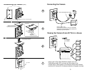
Using an All in One Video Distribution System such as a
ChannelPlus model 3015, you may view the camera on an
unused UHF or cable channel. (For example, the front door camera
could be UHF channel 50. All antenna channels will appear normally.)
Connecting the Camera
Viewing the Camera From All TVs in a House