


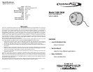

INTRODUCTION
The 7400 camera is available in White or Black. The surface-mount unit allows for
discrete, attractive CCTV camera installation.
INSTALLATION
The surface-mount hardware included with the camera allows easy installation in
almost any situation, including retro-fit applications. Provisions must be made for
physical wire connections, but the camera assembly itself is simply screwed in
place.
1. Drill a 3/4” diameter hole in mounting surface to accommodate wiring.
2. Mount the main bracket in the desired location using three 1-1/4” screws.
3. Feed the camera leads through hole in mounting surface. Connect wires (see
WIRING).
4. Place assembled camera housing into main bracket.
5. Place dome over camera housing and attach to main bracket with three 1/2”
screws. Do not tighten completely.
WIRING
The camera requires RG6 or RG59 coax cable to distribute the video signal to a
monitor’s or modulator’s video input. Use the power supply provided for proper
operation. No additional cable or wire is shipped with the 7400 Series cameras.
1. The camera supplies video through the yellow female RCA connector. If required,
use an RCA-to-F adapter (not included) to connect RG6 or RG59 video cable to
the camera’s video connector.
2. The camera receives power from the power supply through a female mini-jack.
Connect power to the camera using one of the following two options:
a. If the power supply can be located near the camera, connect the power
supply’s mini-plug directly to the camera’s mini-jack.
b. If the power supply cannot be located near the camera, cut the power supply
wire a few inches back from the power supply’s mini-plug. Strip both ends
of the wire and connect a length of 18 AWG 2-conductor wire between the
mini-jack and the power supply’s wire. Solder the connections and insulate
with electrical tape or use wire nuts.
✶ IMPORTANT! OBSERVE PROPER POLARITY when extending the power
wire. Power supply wire polarity marking: White Stripe = (+)
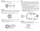
ADJUSTMENT
1. After wiring, make provisions to view the camera image.
2. Adjust the camera to point it at the desired location. Make sure image is level!
3. With the camera properly aimed, tighten the screws.
1
2
USE 1/2" SCREWS
1. ADJUST VIEW
2. TIGHTEN SCREWS
USE 1-1/4" SCREWS
VIDEO OUT
FROM
CAMERA
12 VD
C
POWER
TO CAMERA
BLACK FEMALE
MINI-JAC
K
MALE
MINI-PLUG
MALE RCA
TO FEMALE
TYPE-F ADAPTO
R
(NOT
INCLUDED)
TO VIDEO MONITOR OR
CHANNEL PLUS MODULATOR INPU
T
YELLOW FEMALE
RCA CONNECTO
R
MALE
F-CONNECTOR
12
VDC 300mA
POWER SUPPLY
TO EXTEND POWER SUPPLY CONNECTION,
USE 18 AWG 2-CONDUCTOR WIRE
OBSERVE POLARITY
7400 SERIES
VIDEO CAMERA
WHIT
E
STRIPE = (+
)
MAIN
BRACKE
T
CAMERA DOME
CAMERA COMPONENTS