


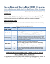

PowerEdge M710/R710/T710
Figure 1: This is the physical memory layout on the R710/M710/T710 (technical schematic).
White tabs indicate first slot of each channel.
************************
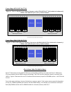
PowerEdge M610/R610/T610
Figure 2: This is the physical memory layout on the M610/R610/T10 (technical schematic).
White tabs indicate first slot of each channel.
************************
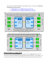
Overview Intel Architecture
Dell 11
Th
Generations servers (610 & 710 Series) released March 2009 use the new Intel® Xeon™ 5500 series
CPUs that support the new DDR3 memory technology. Each CPU has three separate memory controller hubs
(MCHs). Figure 1 illustrates this new CPU architecture and memory layout for 18 DIMM systems – the 710 Series
servers.
Due to this new technology, there are limitations on memory speed. Total system memory speed is dependent
on the CPU, DIMMs populated per channel, and the DIMM ranking. For example, one restriction is that Quad
Rank (QR) DIMMs must be the first DIMM installed in a channel (memory bank #1).*
A1 A4 A7 A2 A5 A8 A3 A6 A9 B9 B6 B3 B8 B5 B2 B7 B4 B1
Memory Channels
Memory Channels
Ch 1
Ch 1
Ch 2
Ch 3
Ch 3
Ch 2
CPU A
CPU B
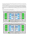
A1 A4 A2 A5 A3 A6 B6 B3 B5 B2 B4 B1
Ch 1
Memory Channels
Memory Channels
Ch 1
Ch 2
Ch 3
Ch 3
Ch 2
CPU B
CPU A