


Pegasus Fast Start Guide 7460572 Rev A Page 2 of 12
CONNECTORFUNCTIONS
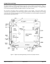
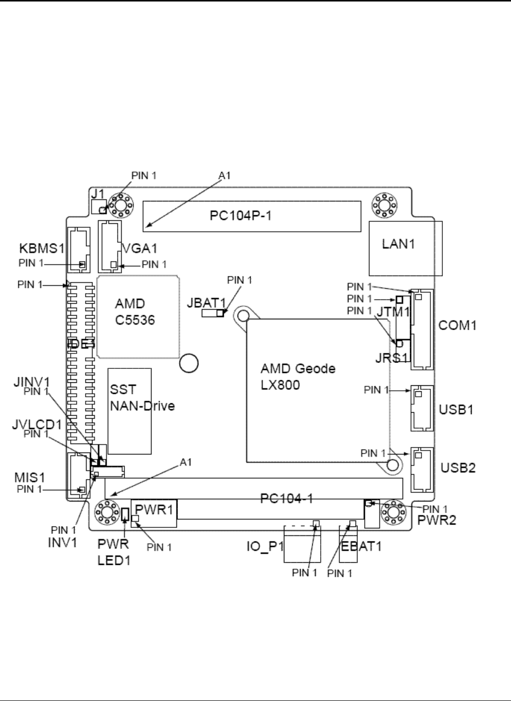
TheboardconformstoPC/104specificationsforthefourcornersandfourmountingholes.Wings,or
extensionsontheleftandrightsides,provideadditionalroomforI/O connectors.Thewingsextend
0.25”pastthestandardPC/104boardedgesasshownintheFigure1below.
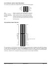
The connector and jumper
layout is provided in Figures 1 and 2 below.This layout enables most
connectorsto bepositionedin theboard wingsand also providessufficient clearancefor themating
connectorswhenlatchingconnectorsareused.AllI/OconnectorsareverticalexceptforthepowerI/O,
externalbatteryandoptionalRJ‐45.
Figure1.Pegasustopdrawingshowingconnectorandjumperlocations