Fairchild Imaging, Inc., 1801 McCarthy Blvd., Milpitas, CA 95035 • (800)325-6975 • (408) 433-2500
FEATURES
• Single channel DC restored video
• Small sealed enclosure
• Remote operation (200 ft.)
• Dynamic range 2000:1 minimum
• Video data rates to 20 MHz
• Precise sensor alignment
• AR coated window sensor (optional)
CAM 1250
CAM 1350
CAM 1550
Line Scan Camera
GENERAL DESCRIPTION
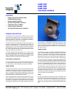
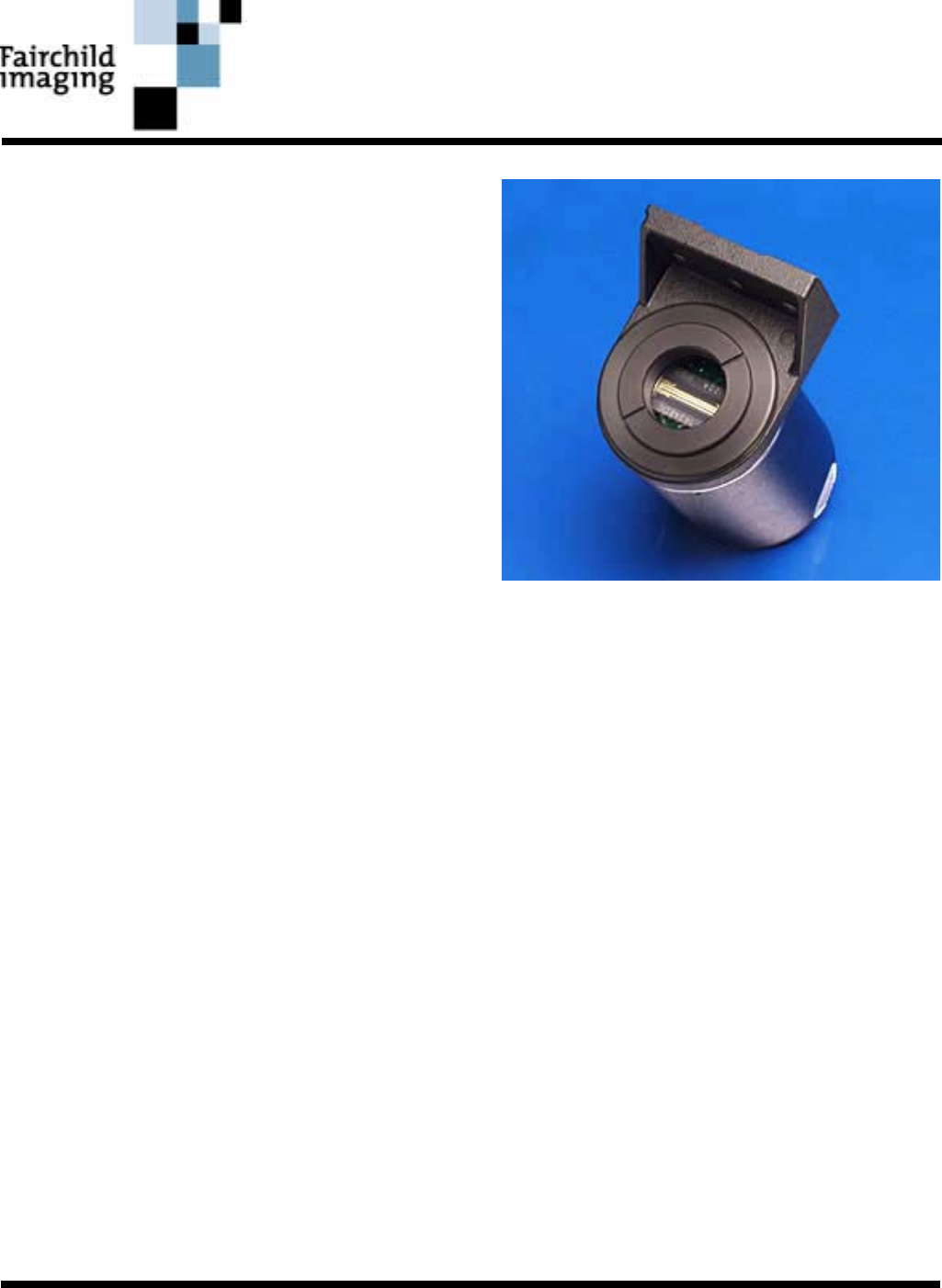
The CAM1X50 is a new generation of modular line scan cameras
designed for incorporation into non-contact electro-optical measure-
ment and process control systems. It is available in 512 1024, or
2048 pixel resolutions. Either single or dual video output channels,
with or without DC restoration, can be supplied.
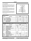
To operate the camera, two differential clock inputs and power are
required. A DATA RATE clock with frequencies up to 20 MHz, will
determine the video data rate. A LINE RATE clock controls the
camera scan rate. The camera outputs a LINE SYC and DATA
RATE differential signals for system interfacing and synchroniza-
tion. These signal lines should use properly terminated, shielded
twisted pair cabling for interconnection.
The camera requires power supply inputs of +5, +15 and -15 volts
DC, internal regulators and filters provide noise immunity for the
CCD sensor bias voltages. The 75Ω source impedance analog
video is available on two coaxial connection as a single or dual
(odd/even) channel of unrestored or DC restored video.
FUNCTIONAL DESCRIPTION
The circuitry within the camera is comprised of differential line driv-
ers and receivers, timing control logic, a CCD linear imaging sen-
sor, DC restoration, video combining, output gain and buffering.
IMAGE SENSOR
The Charge Coupled Device (CCD) used in the CAM1X50 is a high
speed linear imaging sensor with 512, 1024 or 2048 photoelements.
This device is a monolithic component containing a single row of
13µm x 13µm light sensing elements (photosites or pixels), two
analog shift registers, and two output sense amplifiers that provide
separate odd and even channels of sensor video.
Light energy detected by the photosites generate electron charge
packets proportional to the product of integration time and incident
light intensity. Periodically the collected photosite charge packets
are transferred in parallel to their respective odd and even analog
shift registers in response to a low to high transition of the φX sen-
sor input signal. The shift registers, clocked by the sensor φT input,
deliver the charge to packets to a charge sensing amplifier where
they are converted to proportional voltage levels. This synchronous
stream of analog voltage levels is available on the sensor VIDEOOUTA
and VideoOUTB pins.
CAMERA TIMING
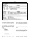
The CAM1X50 is driven by supplying two differential RS-422 like
clocks. The DATA RATE clock input will determine the video pixel
output rate. The LINE RATE clock input controls the camera expo-
sure and scanning rate. The frequency of the LINE RATE clock
determines the camera scan rate, while the interval between suc-
cessive clocks is the period for which the CCD has integrated light.
The camera outputs a LINE SYNC and DATA RATE differential sig-
nals are used for system interfacing. LINE SYNC indicates the start
of a new scan readout and always precedes the first active pixel by
23 clocks. The DATA RATE output is used as a digitize clock for an
A/D to accommodate propagation delays due to long cable lengths.
The differential line driven clock inputs are converted into TTL levels
within the camera by differential line receivers. Single ended TTL
input clocks may be used at low data rates for short cable lengths if
the negative clock input is biased at +1 volt. Operating the camera
in this single ended mode is not guaranteed and camera performance
varies with application implementation.
VIDEO
The two video outputs of the CCD sensor are DC restored on the
dark reference cells that precede each scan line. The video is com-
bined into a single channel of sequential pixels with a high speed
video switch. The video is then inverted and amplified to provide a
positive 1 volt peak signal at sensor saturation when terminated into
75Ω.


