


46 Netfinity 3500-M20 – Type 8657 Models 21Y, 22Y, 31Y, 32Y,
Note: The illustrations in this document might differ slightly
from your hardware.
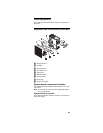
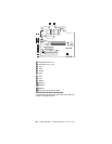
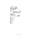
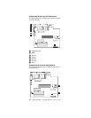
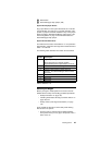
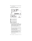
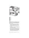
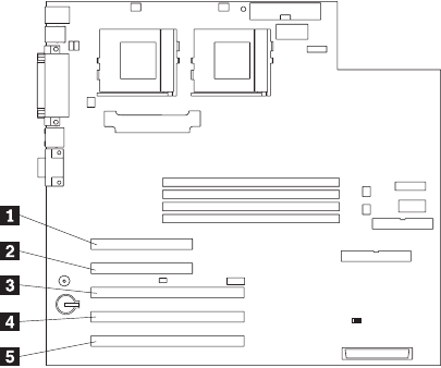
The following illustration shows the location of the 33 MHz
PCI expansion slots on the system board.
1 PCI slot 1 32-bit 33 MHz (J29)
2 PCI slot 2 32-bit 33 MHz (J31)
3 PCI slot 3 64-bit 33 MHz (J35)
4 PCI slot 4 64-bit 33 MHz (J39)
5 PCI slot 5 64-bit 33 MHz (J40)
Adapter considerations
Before you install adapters, review the following:
• Locate the documentation that comes with the adapter
and follow those instructions in addition to the instruc-
tions given in this chapter. If you need to change the
switch or jumper settings on your adapter, follow the
instructions that come with the adapter.
• You can install full-length adapters in all expansion
slots.
• You can install a 32-bit adapter in any of the PCI slots,
but you might want to install it in a 32-bit slot and use
the 64-bit slots for 64-bit adapters.
• Your server supports 5.0V and universal PCI adapters;
it does not support 3.3V adapters.
• Your server uses a rotational interrupt technique to con-
figure PCI adapters. Because of this technique, you
can install a variety of PCI adapters that currently do
not support sharing of PCI interrupts.
• PCI slots 1 and 2 are on PCI bus A and PCI slots 3, 4,
and 5 are on PCI bus B.