


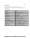

Form Number TM61310 Rev 2 Aug 2007
Page 12
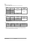
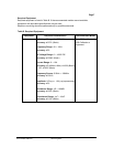
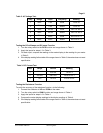
Table 4: Resistance Test:
Step
Range
Source Reading
1
*200 OHM
2.0Ω 1.6 to 2.4
2
*200 OHM
190.0Ω 188.3 to 191.7
3
2K OHM
1.900K 883 to 1Ω 1. .917
4
20K OHM
19.00K 18.83 to 19.17 Ω
5
200K OHM
190.0K 188.3 to 191.7 Ω
7
20M OHM
19.00M 18.40 to 19.60 Ω
*Lead resistance on the 200 ohm range is not included in error.
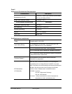
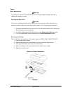
Checking the Diode Test Function
To check the diode test function, do the following:
1 n the meter. . Connect the calibrator to the V and COM inputs o
2. Turn the rotary switch to
.
3. Apply 1.500V DC. The meter display should read approx. 1.500V dc.
e Function
to
To verify the accuracy of the Temperature function, perform the Following:
teps 1 - 7 to the VTemp and COM inputs using a
.
2. Turn the rotary switch to ºC or ºF (Range is –20 to 750 ºC or –4 to 1382 ºF)
3. Compare t reading eter dis reading in
Note : Meter sele the pro tom h meas few seconds.
4. If the display reading falls o tside of the range wn in step meter
does not meet specification.
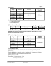
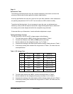
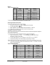
Table 5: Temperature Test:
Reading
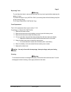
4. Apply a 20-ohm resistor to the meter, the built-in buzzer buzzes.
Testing the Temperatur
Before beginning this test allow 30 minutes for the meter and calibrator temperature adapter
reach ambient temperature.
1. Apply the temperatures in s
temperature adapter to the meter
he on the m play to the Table 4.
cts per range au atically. Eac
sho
urement takes a
s 1–7 of Table 4, the u
Step
Range
Source
1
ºC
-20 ºC -30 to -10
2
ºC
0 ºC -10 to 10
3
ºC
400 ºC 391 to 409
4
ºC
750 ºC 721 to 779
5
ºF
-4 ºF -23 to 15
6
ºF
32 ºF 13 to 51
7
ºF
1382 ºF 1328 to 1436