


CChheecckkiinngg CCoonnttrroollss
Once the housing has been closed, make sure the housing
controls line up with the corresponding camera controls. If the
housing controls are misaligned slightly, make sure the camera
hold down bolt has been tightened down firmly so the camera
is flat against the tray.
TTuurrnn CCaammeerraa OOnn
Turn the camera on and operate each of the housing controls to
get a feel for using the camera in the housing. Take a few pictures
above water with the camera in the housing.
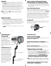
ZZoooomm CCoonnttrrooll
(NOTE:) After you have used the
housing's zoom control, it must be
returned to the center position to
disengage. If the housing zoom
control is pushing the zoom lever
in either direction, you may not
be able to take a picture or access
any other function because the
camera is receiving a signal from
the engaged zoom control.
CClloossiinngg tthhee HHoouussiinngg
1. Place housing face down in your
lap or on flat surface.
2. Check to see that there is an
o-ring on the housing back and
that it is clean and in its proper
location.
3. Guide the back into the housing
front. The o-ring should touch the
housing all the way around. There
should be an even gap all the way
around between the housing and
the housing back.
4. Lift the lid snaps so they are
extended and place each lid
snap into the corresponding hook
on the housing back.
5. To close the housing, push
down on the lid snaps until
they snap into place . Lid
snaps on opposite sides of the
housing should be closed at the
same time. Be sure they are down
far enough to engage the lock.
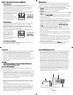
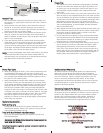
DDoouubbllee cchheecckk
- Once the housing is closed, check the o-ring seal.
Check the gap between the housing back and the housing. It
should be even all the way around the housing.
Look through the clear plastic back at the o-ring. You should see
a darkened area where the o-ring is compressed against the
housing back. If you do not see an even black compression seal
all the way around the back, open the lid snaps, reseat the
housing back and close the lid snaps. Visually check the seal again.
o-ring
housing back
housing back
o-ring
even gap
all 4 sides
6
7
Engaged Center Position
Disengaged
+
-
-
+
5
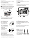
CCAAUUTTIIOONN::
Some camera tripod socket threads are plastic. The mounting
tray bolt is metal. Do not cross thread or over tighten as you
may damage the camera tripod socket threads.
CAMERA / MOUNT
O' Ring
Lid
Hook
Mounting Bolt
Mounting
Tray
Canon
G10
I
I
n
n
s
s
t
t
a
a
l
l
l
l
i
i
n
n
g
g
t
t
h
h
e
e
C
C
a
a
m
m
e
e
r
r
a
a
(
(
c
c
o
o
n
n
t
t
.
.
)
)
5. Using a coin or screwdriver (preferred), secure the camera with
the mounting bolt which threads into the camera’s tripod
socket
((DDiiaaggrraamm BB))
.
Diagram B
8
I
I
n
n
s
s
t
t
a
a
l
l
l
l
i
i
n
n
g
g
t
t
h
h
e
e
C
C
a
a
m
m
e
e
r
r
a
a
1. Pull out on each housing control until it stops. This will get the
controls out of the way for installation of the camera.
2. Remove the back from the housing.
3. The mounting tray for the camera is secured to the housing
back. Position the camera on the tray.
4 Slide the housing Hotshoe Connector into the Camera Hothoe
Mount
(
(
D
D
i
i
a
a
g
g
r
r
a
a
m
m
A
A
)
)
.
Slide the connector forward until it stops.
This should be done before the camera is secured with the
mounting bolt
(
(
P
P
a
a
g
g
e
e
#
#
6
6
-
-
D
D
i
i
a
a
g
g
r
r
a
a
m
m
B
B
)
)
.
N
N
O
O
T
T
E
E
:
:
If your are using an EV Controller and NOT hard-wiring your
strobes directly to the housing, leave the housing hotshoe
disconnected from the camera. You will also need to install the
Flash Deflector (supplied) over the back of the housing port to
b
lock and deflect the camera flash to the EV controller.
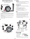
E
xternal Strobe Connector
Waterproof Cap
(
Do not remove underwater)
O-ring
H
ousing Back
Hot Shoe Connector
M
ounting
Tray
C
C
a
a
u
u
t
t
i
i
o
o
n
n
:
:
Do not remove the External Strobe Connector Waterproof Cap
unless an external sync cord is going to be plugged in. Do not
remove the Waterproof C ap or Sync Cord underwater.
Diagram A