


5
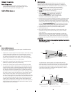
External Strobe
C
onnection/
Waterproof
C
ap
O
'ring
Housing Back
H
ousing Hot
S
hoe Connector
C
amera Hot Shoe
Camera
F
F
l
l
a
a
s
s
h
h
C
C
o
o
n
n
n
n
e
e
c
c
t
t
i
i
o
o
n
n
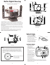
When using an external strobe connect the housings Hot Shoe
Connector slide the connector into the hot shoe of the camera
from the back as shown Slide the connector forward until it
stops This can be done after the camera is secured with the
mounting bolt
N
N
O
O
T
T
E
E
:
:
The housing’s External TTL Strobe Connector’s waterproof cap
should only be removed when connecting an external strobe
with a sync cord If no sync cord is connected to the housing
the connector’s waterproof cap must be in place before using
the housing in the water
6
C
C
l
l
o
o
s
s
i
i
n
n
g
g
t
t
h
h
e
e
H
H
o
o
u
u
s
s
i
i
n
n
g
g
Check to see that there is an o’ring
on the housing back and that it is
clean and in its proper location
Guide the back onto the housing
T
ake care to see that the TTL sync
cord does not obstruct the
installation
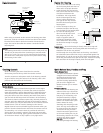
The o’ring should
touch the housing
all the way
a
round There should be an
even gap all the way around
b
etween the housing and the
housing back
Lift the lid snaps so they are
extended and place the lid snap
into the hook on the housing back
To close the housing push
d
own on the lid snaps until
they snap into place Lid
snaps on opposite sides of
the housing should be closed
at the same time Be sure they
are down far enough to engage
the lock
D
D
o
o
u
u
b
b
l
l
e
e
c
c
h
h
e
e
c
c
k
k
Once the housing is closed check the o’ring seal
Check the gap between the housing back and the housing it
should be even all the way around
Look through the clear plastic back at the o’ring You should
see a darkened area where the o’ring is compressed against the
housing back If you do not see an even black compression seal
all the way around the back open the lid snaps reseat the housing
back and close the lid snaps Visually check the seal again
o’ring
housing back
housing back
housing
housing
o’ring
even gap
all 4 sides
7
C
C
h
h
e
e
c
c
k
k
i
i
n
n
g
g
C
C
o
o
n
n
t
t
r
r
o
o
l
l
s
s
Once the housing has been closed check to see that
the housing controls line up with the camera controls
Turn the camera on and operate each of the housing controls
to get a feel for using the camera in the housing Take a few
pictures with the camera in the housing
C
C
A
A
U
U
T
T
I
I
O
O
N
N
:
:
S
S
h
h
u
u
t
t
t
t
e
e
r
r
R
R
e
e
l
l
e
e
a
a
s
s
e
e
The camera's shutter release button operates in two stages
When depressed halfway it activates the camera's exposure
meter and autofocus When depressed fully it takes the picture
This half stop of the shutter release is more easily felt when
using the camera out of the housing But with some practice
you can feel the half stop when the camera is in the housing
The camera's shutter release requires only minimal pressure to
activate With the additional leverage of the housing’s shutter
release control you can put undue force on the camera's shutter
release button This can result in damage to the camera
Digital cameras have a noticeable lag time between when you
push the shutter release button and when the camera starts to
do something It is human nature to push harder when the
camera
does not instantly respond Take several pictures with
the camera
in the housing paying special attention to the feel
of the shutter release It only requires a very light touch
Q
Q
u
u
i
i
c
c
k
k
R
R
e
e
l
l
e
e
a
a
s
s
e
e
B
B
a
a
s
s
e
e
H
H
a
a
n
n
d
d
l
l
e
e
s
s
a
a
n
n
d
d
T
T
r
r
a
a
y
y
Q
Q
u
u
i
i
c
c
k
k
R
R
e
e
l
l
e
e
a
a
s
s
e
e
B
B
a
a
s
s
e
e
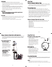
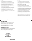
The QuickRelease Base is plastic
A toggle lever located underneath
the base allows the base to be
easily removed from
the Tray
Turn the housing upside down
pull out on the toggle lever
Rotate the lever ° to remove
the base
H
H
a
a
n
n
d
d
l
l
e
e
s
s
a
a
n
n
d
d
T
T
r
r
a
a
y
y
The handles on the housing are
rubber and the tray is aluminum
Their weight helps to offset the
buoyancy of the housing The
complete assembly is slightly
negative
underwater for better
control
The handles have a push
button
release for easily
attaching and removing strobe
arms The tray and handles can
be removed from the housing
To remove the
tray the base
must be removed
to gain access
to the nuts holding the tray on
the housing Remove the nuts
washers and rubber spacers
D
D
O
O
N
N
O
O
T
T
remove the bolts
protruding through the housing
Quick Release Base
Slot
Flip Quick Release
Lever Up
Rotate Quick
Release Lever
Remove Quick
Release Lever
and Base
BASE QUICK RELEASE
8