


EN Camera Series
34 Connectors and Cables
5 Connectors and Cables
5.1 Connector Pin Configurations
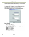
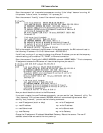
5.1.1 12-Pin Connector
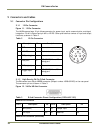
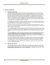
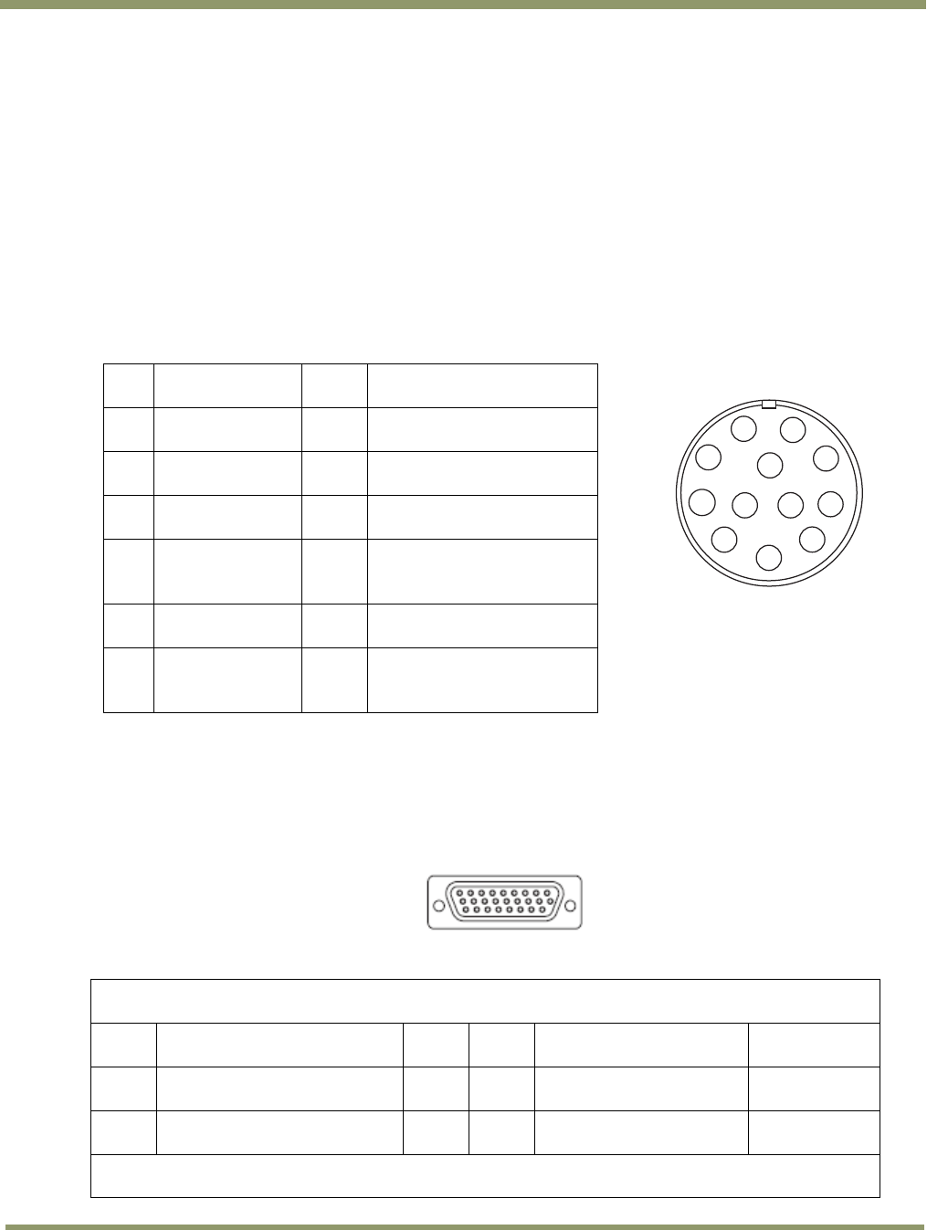
Figure 11. 12-Pin Connector
The JAI EN camera has a 12-pin Hirose connector for power input, serial communication, and signal
integration. Pin #1 is Ground and pin #2 is +12V DC. Other pins handle a number of input and output
functions, as shown in Table 2.
Table 2 12-Pin Connector
Pin Description Pin Description
1 GND 7 Reserved
2 +12V DC 8 Flash strobe output
3 GND (analog) 9 Reserved
4 Test point 10
RXD (RS-232) Power PC
debug port
5 GND (digital) 11 Reserved
6 Trigger input* 12
TXD (RS-232) PowerPC
debug port
5.1.2 High-Density 26-Pin D-Sub Connector
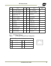
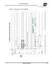
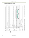
The EN camera has a 26-pin MDR26 connector (3M part number 10226-6212VC) on the rear panel.
The connector pin-out is shown in Table 3.
Figure 12. 26-Pin HD-Sub Connector
Table 3 D-Sub Connector Pinout Configuration (10226-6212 VC)
Camera Link Connector
Pin # Description I/O
Pin #
Description
I/O
1 GND (Power)
14
Tamper Input
In
2 +12V Input Out
15
Reserved
Out
Camera Link Connector (continued)
1
2
3
4
5
6
9
8
7
11
12
10