


POWER SOURCE CONNECTION
Use the provided AC Adapter.
AV CABLE CONNECTION
● Use the provided 1.5 m AV cable.
● For longer distance connections, use the optional AV extension
cable (JVC No. VC-V3731J/20 m) as well.
ATTACHING THE CAMERA TO THE
CEILING
● Use the optional ceiling mount kit (JVC No. CU-V602J).
● Be sure to refer to its instruction manual during installation.
©
1997 VICTOR COMPANY OF JAPAN, LTD.
SPECIFICATIONS
TV system : NTSC
Total pixels : 537 (H) x 505 (V)
Effective pixels : 510 (H) x 492 (V)
Horizontal resolution : 310 TV Lines
S/N raito :
46 dB
Minimum illumination : 12 lx
Video output signal : 1.0 Vp-p/75 Ω (composite video
signal)
Output connector : RCA pin jack
Focus range : Manual adjustment 5 cm —
AC adapter input voltage : DC 9 – 12 V
Power consumption : Approx. 2 W
Microphone : Non-directional electret condenser
Dimensions : 100 (W) x 61 (H) x 100 (D) mm
Weight : Approx. 150 g
Provided Accessories
AC Adapter, AV Cable (1.5 m)
Optional Accessories
AV Cable : VC-V3731J (20 m)
Installation Adapter : CU-V602J
E. & O. E. Design and specifications subject to change without notice.
OPERATION
ON
• •
I
POWER
OFF
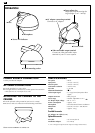
Ⅲ Video and audio output terminal
Connect to video and audio input
terminal of your TV set or system.
Ⅲ Focus adjust ring
Adjust the focus by turning the
ring left/right (5 cm – infinity)
Ⅲ Microphone
Ⅲ Power LED indicator
Ⅲ Tripod mounting socket
Ⅲ Lens
Ⅲ AC adapter connecting terminal
Connect to AC adapter.
Ⅲ Power switch
ENEN