


EN59
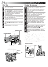
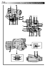
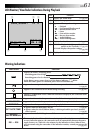
Controls
1 Battery Release Switch
[BATTERY RELEASE] .............................. ੬ pg. 7
2 PUSH OPEN Button............................... ੬ pg. 9
3 Video Light Switch
[LIGHT OFF/AUTO/ON]...................... ੬ pg. 15
4 OPEN/EJECT Switch ............................... ੬ pg. 9
5 Snapshot Button [SNAPSHOT] ............. ੬ pg. 17
6 •Power Zoom Lever [T/W] .................. ੬ pg. 14
•Speaker Volume Control [VOL.] ........ ੬ pg. 29
7 •MENU/BRIGHT Dial
[+, –, PUSH] ................................. ੬ pg. 8, 18
•LCD Monitor/Viewfinder Brightness
Control ............................................. ੬ pg. 12
8 Snapshot Mode Button [MODE] ........... ੬ pg. 17
9 Recording Start/Stop Button.................. ੬ pg. 12
0 Power Switch [ , OFF, , ] ...... ੬ pg. 13
! Rewind Button [REW] .......................... ੬ pg. 29
@ Stop Button [STOP] .............................. ੬ pg. 29
# Fast-Forward Button [FF] ...................... ੬ pg. 29
$ Play/Pause Button [PLAY/PAUSE] ......... ੬ pg. 29
% Diopter Adjustment Control ................. ੬ pg. 11
Connectors
The connectors
^
to
e
are located beneath a cover.
^
Video Output Connector ...................... ੬ pg. 32
& Audio Output Connector [L] ................ ੬ pg. 32
* S-Video Output Connector ................... ੬ pg. 32
( Audio Output Connector [R] ................ ੬ pg. 32
) DC IN Connector................................... ੬ pg. 7
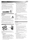
q J Terminal [JLIP (Joint Level Interface Protocol)
Connector] .......................................... ੬ pg. 43
•Connect the editing cable when performing
Random Assemble Editing (੬ pg. 42 – 47).
•It is used to connect the camcorder to a device
such as a personal computer.
For further details, consult your nearest JVC
dealer.
•JLIP-controlled editing from the camcorder to a
VCR is not possible if the VCR is not equipped
with a J terminal.
w PC Connector ...................................... ੬ pg. 34
It is used to connect the camcorder to the serial
port of a personal computer.
For further details, consult your nearest JVC
dealer.
e Digital Video Connector
[DV IN/OUT] (i.link*) .................... ੬ pg. 35, 37
* i.Link refers to the IEEE1394-1995 industry
specification and extensions thereof. The logo
is used for products compliant with the i.Link
standard.
Indicators
r Power Lamp ........................................ ੬ pg. 13
Other Parts
t Battery Pack Mount ............................... ੬ pg. 7
y •Camera Sensor
Be careful not to cover this area; a sensor
necessary for shooting is built-in here.
•Remote Sensor .................................. ੬ pg. 38
u Video Light .......................................... ੬ pg. 15
i Stereo Microphone .............................. ੬ pg. 48
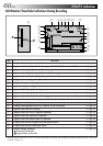
o Viewfinder ........................................... ੬ pg. 11
p Speaker ............................................... ੬ pg. 29
Q Shoulder Strap Eyelets .......................... ੬ pg. 11
W Grip Strap ............................................ ੬ pg. 11
E LCD Monitor ....................................... ੬ pg. 12
R Tripod Mounting Socket ....................... ੬ pg. 11
T Stud Hole ............................................ ੬ pg. 11