


EN 95
Master Page: Right
GR-DVM96-76U_80-103.fm Page 95
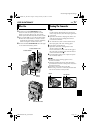
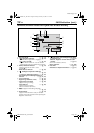
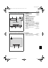
Controls
a •Power Zoom Ring [T/W].................... ੬ pg. 20
•Speaker Volume Control.................... ੬ pg. 22
b Recording Start/Stop Button................ ੬ pg. 19
c Power Switch [A, M, P, OFF].......... ੬ pg. 14
d Lock Button ......................................... ੬ pg. 14
e •Snapshot Button [SNAPSHOT] .... ੬ pg. 27, 53
•Information Button [INFO] ............... ੬ pg. 30
f •E-Mail Clip Recording Button [E-MAIL]
(GR-DVM96 only)........................ ੬ pg. 60, 61
•Index Button [INDEX] .......... ੬ pg. 30, 59, 71
g •Menu Wheel [MENU, +,–]................. ੬ pg. 38
•LCD Monitor Brightness Control
[BRIGHT, +,–].................................... ੬ pg. 13
h Battery Release Tab [BATT.RELEASE].... ੬ pg. 10
i Cassette Open/Eject Switch
[OPEN/EJECT]...................................... ੬ pg. 16
j •Play/Pause Button [4/9] .................. ੬ pg. 22
•Backlight Compensation Button
[BACKLIGHT] .................................... ੬ pg. 57
k •Fast-Forward Button [5]................ ੬ pg. 22
•Night-Alive Button [NIGHT].............. ੬ pg. 53
l VIDEO/MEMORY Switch
[VIDEO/MEMORY] ............................. ੬ pg. 14
m •Rewind Button [3] ........................ ੬ pg. 22
•Focus Adjustment Button
[FOCUS]............................................ ੬ pg. 55
n •Stop Button [8]................................. ੬ pg. 22
•Digital Sound Button [D.SOUND]
(GR-DVM96 only).............................. ੬ pg. 59
•D.S.C. Playback Select Button [SELECT]
(GR-DVM96 only)...................... ੬ pg. 28 – 34
o Diopter Adjustment Control................ ੬ pg. 12
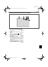
Connectors
The connectors are located beneath the covers.
P S-Video Output Connector
[S-VIDEO]................................ ੬ pg. 24, 62, 74
Q Headphone Connector [ ]
(GR-DVM96 only)................................ ੬ pg. 70
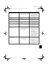
No sound is output from the speaker when
headphones are connected to this connector.
R Edit Connector [EDIT] ........................ ੬ pg. 74
S Audio/Video Output Connector
[AV]......................................... ੬ pg. 24, 62, 74
T DC Input Connector [DC] ............. ੬ pg. 10, 11
U USB (Universal Serial Bus)
Connector .......................................... ੬ pg. 78
V Digital Video Connector [DV IN/OUT]
(i.Link*).................................... ੬ pg. 63, 64, 78
* i.Link refers to the IEEE1394-1995 industry
specification and extensions thereof. The logo
is used for products compliant with the i.Link
standard.
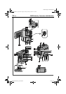
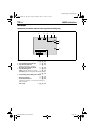
Indicators
A Power Lamp [POWER]....................੬ pg. 14, 19
B Charge Lamp [CHARGE] ......................੬ pg. 10
C Tally Lamp......................................੬ pg. 19, 48
Other Parts
a LCD Monitor..................................੬ pg. 13, 20
b Viewfinder............................................੬ pg. 12
c Viewfinder Cleaning Hatch ..................੬ pg. 91
d Speaker ................................................੬ pg. 22
e Cassette Holder Cover..........................੬ pg. 16
f Grip Belt Eyelet......................................੬ pg. 6
g Camera Sensor
Be careful not to cover this area, a sensor
necessary for shooting is built-in here.
h Stereo Microphone...............................੬ pg. 70
i Lens
j Flash Sensor
Be careful not to cover this area, as it contains a
sensor required by the flash.
k Flash.....................................................੬ pg. 54
l Remote Sensor .....................................੬ pg. 66
m Card Cover [MEMORY CARD] ............੬ pg. 17
n Battery Pack Mount..............................੬ pg. 10
o Stud Hole
p Tripod Mounting Socket .......................੬ pg. 13
GR-DVM96-76U_80-103.fm Page 95 Monday, March 11, 2002 2:50 PM