


EN53
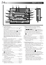
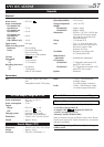
Controls
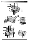
1 Dioptre Adjustment Control ................. ੬ pg. 10
2 Lens Cover Open/Close Ring
[LENS COVER] .................................... ੬ pg. 12
3 Video Light Switch [LIGHT OFF/AUTO/ON]
(GR-AXM405 only) .............................. ੬ pg. 19
4 •Snapshot Button [SNAPSHOT]
(GR-AXM405 only) ........................... ੬ pg. 20
•5-Second Recording Button [5 SEC REC]
(GR-AXM205 only) ........................... ੬ pg. 18
5 •Power Zoom Lever [T/W] .................. ੬ pg. 16
•Speaker Volume Control [VOL.] ........ ੬ pg. 37
6 Picture Stabilizer Button
[P.STABILIZER]..................................... ੬ pg. 18
7 Program AE Button [P.AE]..................... ੬ pg. 22
8 Fade/Wipe Button [EFFECT] ................. ੬ pg. 21
9 •Rewind Button [
2
, REW] ................ ੬ pg. 36
•Retake Rewind Button [RETAKE R]..... ੬ pg. 17
•Quick Review Button [ R] ............. ੬ pg. 17
0 •Fast-Forward Button [
3
, FF] ............ ੬ pg. 36
•Retake Forward Button [RETAKE F] .... ੬ pg. 17
! Stop Button [5 , STOP]......................... ੬ pg. 36
@ Play/Pause Button
[
4
/6, PLAY/PAUSE]............................. ੬ pg. 36
# •Select Dial [+, –, PUSH] ................ ੬ pg. 7, 26
•Bright Dial [BRIGHT] ........................ ੬ pg. 15
$ MENU/DISPLAY Button ................. ੬ pg. 13, 26
% •Counter Reset/Memory Button
[COUNTER R/M] .............................. ੬ pg. 38
•Recording Mode Button [SP/LP]........... ੬ pg. 8
^ EJECT Switch ......................................... ੬ pg. 9
& Recording Start/Stop Button.................. ੬ pg. 12
* Power Switch ................................ ੬ pg. 12, 36
( Battery Release Switch
[BATTERY RELEASE] .............................. ੬ pg. 4
) PUSH Button ......................................... ੬ pg. 9
Connectors
q DC IN Jack ............................................ ੬ pg. 5
The connectors w to r are located beneath the
cover.
w Video Output Connector ...................... ੬ pg. 40
e Audio Output Connector ..................... ੬ pg. 40
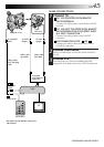
r J Terminal [JLIP (Joint Level Interface Protocol)
Connector]
•Connect the editing cable when performing
Random Assemble Editing (
੬ pg. 44 - 47).
•It is used to connect the camcorder to a device
such as a personal computer.
For further details consult your nearest JVC
dealer.
•JLIP-controlled editing from camcorder to VCR
is not possible if the VCR is not equipped with a
J terminal.
Indicators
t Tally Lamp........................................... ੬ pg. 12
y Power Lamp ........................................ ੬ pg. 12
Other Parts
u Battery Pack Mount ............................... ੬ pg. 4
i Viewfinder ........................................... ੬ pg. 10
o Grip Strap............................................ ੬ pg. 10
p •Camera sensor
Be careful not to cover this area; a sensor
necessary for shooting is built-in here.
•Remote Sensor .................................. ੬ pg. 43
Q Video Light (GR-AXM405 only) ............ ੬ pg. 19
W Microphone......................................... ੬ pg. 49
E Eyepiece
R Speaker ............................................... ੬ pg. 37
T LCD Monitor ....................................... ੬ pg. 15
Y Shoulder Strap Eyelets .......................... ੬ pg. 11
U Clock Battery Slot .................................. ੬ pg. 6
I Tripod Mounting Socket ....................... ੬ pg. 11