


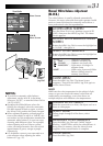
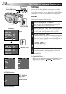


EN 35
There are three basic types of connections. When making
the connections, refer also to your VCR and TV
instruction manuals.
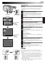
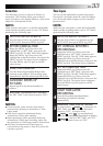
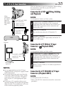
Connection To A VCR
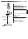
A
(Editing, Dubbing
and Playback)
NOTE:
Use the optional Audio and Video cables.
CONNECT CAMCORDER TO VCR
1
As shown in the illustration at left, connect the
Audio and Video cables between the AUDIO and
VIDEO OUT connectors on the camcorder and
those on the VCR.
SUPPLY POWER
2
Turn on the camcorder, the VCR and the TV.
SELECT MODE
3
Set the VCR to its AUX input mode, and set the TV
to its VIDEO mode.
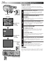
Connection To A TV With A/V Input
Connectors
B
(Playback ONLY)
NOTE:
Use the optional Audio and Video cables.
CONNECT CAMCORDER TO TV
1
As shown in the illustration at left, connect the
Audio and Video cables between the AUDIO and
VIDEO OUT connectors on the camcorder and
those on the TV.
SELECT MODE
2
Set the TV to its VIDEO or AV mode (as specified in
its instructions).
Connection To A TV With NO A/V Input
Connectors (Playback ONLY)
NOTE:
Use the optional RF-V5U RF unit.
* Refer to the RF-V5U instruction manual for connection
procedure.
NOTES:
●
It is recommended to use the AC Power
Adapter/Charger as the power supply instead
of the battery pack.
●
To monitor the picture and sound from the
camcorder without inserting a tape, set the
camcorder’s Power Switch to “CAMERA”,
then set your TV to the appropriate input
mode.
●
If you have a TV or speakers that are not
specially shielded, do not place the speakers
adjacent to the TV as interference will occur
in the camcorder playback picture.
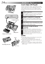
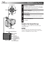
PLAYBACK
Basic Connections
VCR
Antenna
To AUDIO and VIDEO
OUT connectors
To AUDIO and
VIDEO IN
connectors
Audio and Video
cables (optional)
To AUDIO, VIDEO
and RF DC OUT
connectors
RF unit RF-V5U
(optional)
When
connecting
the cables,
open the
jack cover.
(GR-AX847
only)