


EN 55
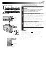
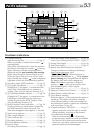
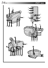
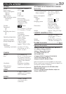
Controls
1 Power Zoom Button ........................... ੬ pg. 18
2 Select Dial ......................................... ੬ pg. 22
3 Multi-Function Control
•EFFECT Button................................. ੬ pg. 24
•WIDE Button ...................................
੬ pg. 25
•TITLE Button ....................................
੬ pg. 26
•SUPER LOLUX Button .....................
੬ pg. 25
4 PUSH Button...................................... ੬ pg. 13
5 Recording Mode [SP/EP] Button ......... ੬ pg. 12
6 DATE/TIME Button ............................. ੬ pg. 20
COUNTER R/M Button.......................
੬ pg. 40
7 P. [Picture] STABILIZER Button ........... ੬ pg. 19
8 REW Button ....................................... ੬ pg. 38
RETAKE R [Quick Review] Button ......
੬ pg. 19
9 PLAY/PAUSE Button ........................... ੬ pg. 38
0 FF Button ........................................... ੬ pg. 38
RETAKE F Button ................................
੬ pg. 19
! STOP Button ...................................... ੬ pg. 38
@ EJECT Switch ...................................... ੬ pg. 13
# Function Navigator Dial
[MENU Jog Dial] ................................ ੬ pg. 11
$ LIGHT OFF/AUTO/ON Switch ........... ੬ pg. 21
% BATT. [Battery] RELEASE Switch ......... ੬ pg. 8
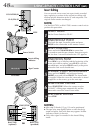
^ Diopter Adjustment............................ ੬ pg. 14
& Recording Start/Stop Button................ ੬ pg. 16
* Power Switch ................................ ੬ pg.16, 38
( LENS COVER Switch.......................... ੬ pg. 16
Connectors
) DC IN Jack......................................... ੬ pg. 9
The jacks q to r are located beneath the jack
cover.
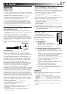
q J terminal [JLIP (Joint Level Interface Protocol)
Connector.]
•Connect the editing cable when performing
Random Assemble Editing (੬ pg. 44 – 47).
•It is used to connect the camcorder to a device
such as a personal computer.
For further details consult your nearest JVC
dealer.
•JLIP-controlled editing from camcorder to VCR
is not possible if the VCR is not equipped with
a J terminal.
w VIDEO OUT Connector ..................... ੬ pg. 37
e RF DC OUT Connector ...................... ੬ pg. 37
r AUDIO OUT Connector .................... ੬ pg. 37
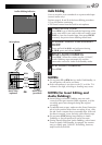
Indicators
t Power Indicator.................................. ੬ pg. 16
y Tally Lamp ......................................... ੬ pg. 16
Other Parts
u Video Light......................................... ੬ pg. 21
i Microphone
o •Camera sensor
Be careful not to cover this area; built-in
here is the sensor necessary for shooting.
•Remote Sensor.................................
੬ pg. 43
p Clock Battery Compartment ............... ੬ pg. 10
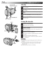
Q Battery Pack Mount ............................ ੬ pg. 8
W Shoulder Strap Eyelets ........................ ੬ pg. 15
E Electronic Viewfinder ......................... ੬ pg. 14
R Grip Strap .......................................... ੬ pg. 14
T Tripod Mounting Socket ..................... ੬ pg. 15